Operating features of the SPECTRONIC~ 20+
spectrophotometer
readout and readjust if necessary.
The main controls for routine operation are the Power
Switch{Ze;ro Control. Wavelength Control. Filter Lever
and Transmittance/Absorbance Control.
.8!!gjQg OutQut Jack
This jack is used to connect an analog recorder to the
instrument (see Figure 1-3). The analog output signal
level is fixed at approximately I VDC at lOO%T. This
output is not adjustable.
Power Switch / Zero Control
The ON-OFF main power switch is operated by the
Power SwitchfZero Control knob. The Zero Control
knob is used to set the display to a O%T readout when
the sample compartment is empty and the adapter cover
is closed.
The signals on each pin are listed below:
1 Analog output
2 Analog ground
3 Analog ground
4 Meter (+)
5 Analog output
6 Meter (-)
Wavelength Control
The Wavelength Control selects the desired analytical
wavelength of the instrument. The selected wavelength
is indicated on the wavelength scale in the window next
to the knob. Red numbers indicate that the 600-950nm
filter should be used; black numbers indicate that the
340-599nm filter should be used. All gradations are in
5-nm intervals.
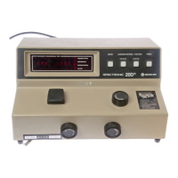
Operating features of the SPECTRONIC~ 20D+
spectrophotometer
The main controls for routine operation are the Power
SwitchfZero Control, Wavelength Control, Filter Lever,
Transmittance/Absorbance Control, the MODE
selector and Factor Adjust controls.
The accessory Analog Output/Serial I/O port is located
on the underside of the instrument, as shown in Figure
1-3.
Filter Lever
This control selects the filter to be used for the
measurement:
.Red is used for measurements from 600 to 950nm.
.Black is used for measurements from 340 to 599nm.
Power Switch / Zero Control
The ON-OFF main power switch is operated by the
Power SwitchfZero Control knob. The Zero Control
knob is used to set the display to a O%T readout when
the sample compartment is empty and the adapter cover
is closed.
~
Readings are taken directly from the meter in either
transmittance or absorbance.
Transmittance / Absorbance Control
This control sets the display to lOO%T (O.OA) when a
cuvette containing a blank reference solution is inserted
in the sample compartment. It must be reset
whenever the analytical wavelength has been
changed. When operating at a fixed wavelength for an
extended period of time, check the 100% T (O.OA)
 Loading...