SECTION III CONTROLS, CONNECTORS AND INDICATORS
3.1 GENERAL
All operating controls, connectors and indicators are described in
Table 3-1. Become familiar with each item prior to operating the
radiometer for the first time.
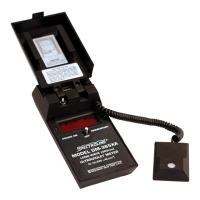
TABLE 3-1 FRONT AND BACK PANEL DESCRIPTION
1. Power Switch: With the dual-operation toggle switch flipped to
the ‘‘POWER ON’’ position, the radiometer will
remain activated until manually turned off. The
meter will also operate when the switch is held in
the ‘‘MOMENTARY’’ position, but the switch will
automatically return to the ‘‘OFF’’ position once
pressure is released.
2. Numerical Display: The digital display uses LEDs and includes a ‘‘1’’
digit and 7-segment type 0-9 digits. The last digit is
permanently set at ‘‘0.’’ Over-range (or out-of-
range) condition is indicated by a blank display,
except for the most significant ‘‘1.’’
3. Retractable Cord: This coil cord connects the sensor to the readout
unit.
4. Charger Jack: Use only with rechargeable battery cells. Any
other type of cell may produce hazardous condi-
tions and may damage the instrument.
5. Sensor Window: Sapphire diffuser to ensure good cosine response.
6. Battery Level When lighted, green LED indicates that battery
Indicator Light level is adequate.
(Not Illustrated)
6