Also, interference filters are not perfect band-pass filters. Therefore, if an
inappropriate measurement is attempted (for example, measurement of
small amounts of UV-B from an intense UV-A radiation source or mea-
surement of relatively small amounts of UV-A, UV-B or UV-C in sunlight),
errors can be expected if appropriate corrections are not made.
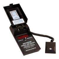
4.2.1 REMOTE USE OF THE SENSOR
To Remove Sensor: First, release cord from retaining slot. Then slide
sensor out. Do not pull out sensor without first
releasing cord, to avoid stretching of cord.
To Replace Sensor: Slide sensor up into receptacle with cord down
and filter up. Wrap cord clockwise around
retaining slot. See diagram inside front cover of
radiometer.
SECTION V THEORY OF OPERATION
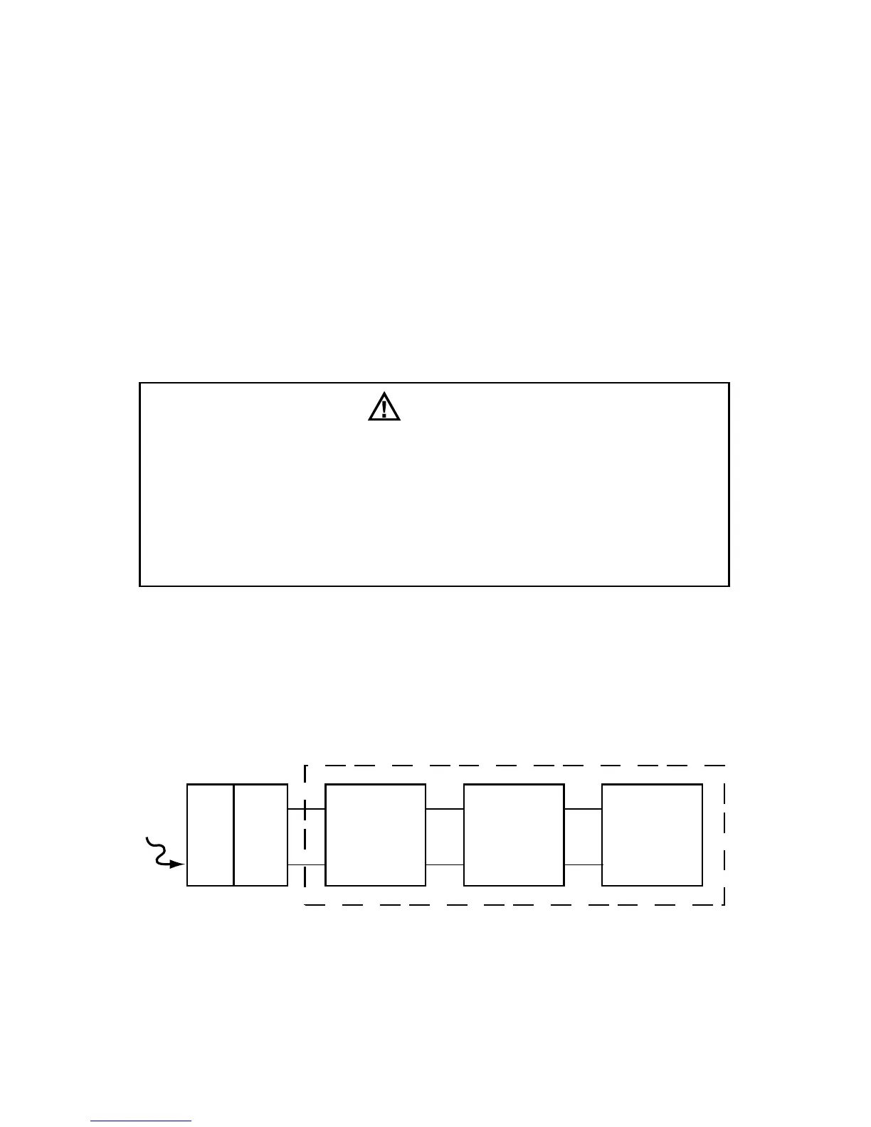
5.1 OVERALL SYSTEM
The basic block diagram for the radiometer is shown in Figure 5-1.
Figure 5-1 Basic System Block Diagram
5.1.1 THE INPUT OPTICS
The Lambertian (Cosine) response of the sensor head is desirable for
many measurement applications, especially those where the angle
from the source to the detector is variable or those situations where
CAUTION
This radiometer is designed for intermittent use only. Do not
leave the exposed sensor head under the light source any longer
than necessary to take measurements. Prolonged exposure
can result in premature aging and/or solarization of the sensor,
necessitating more frequent recalibration to maintain accurate
readings. In time, such exposure can cause permanent damage to
the sensor.
8