Spectrum Digital, Inc
1-4 XDS510PP MPSD Emulator Pod Installation Guide
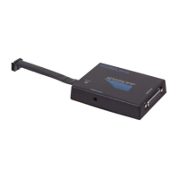
1.3 Step 2: Connecting the XDS510PP to Your Target System
Figure 1-1 shows how you connect the XDS510PP emulator pod and 25 conductor
cable to your target system. In most cases, the target system will be a target board
of your own design.
Figure 1-1. Connecting the XDS510PP Emulator Pod to Your Target System
Esc Num Scroll Sys
Lock Lock Req
789
456
123
Home PgUp
End PgDn
0.
Ins Del
+
-
PrtSc
*
Break
Ctrl
Shift Shift
Alt
Caps
Lock
Enter
~ ! @ # $ % ^ & * ( ) _ + |
`1234567890-=\
QWE R TYU IOP
ASDFGHJKL
ZXCVBNM
{}
[]
:"
;'
<>?
,./
F1 F2
F3 F4
F5 F6
F7 F8
F9 F10
C3X DSP
12- pin connector
D-sub connector
25-pin male
XDS510PP Emulator Pod
25 Conductor Cable
port on PC)
(Plugs into parallel
D-sub connector
25 pin male
12 - pin header
XDS510PP
ACTIVE
POWER [5VDC]
P
R
I
N
T
E
R
P
O
R
T
for example