2
6
5
4
3
1
2
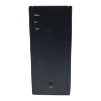
Overview
Installation
Desktop:
1 Using a screwdriver, remove the screw on the bottom of BB24V1U.
2 Slide o the battery cover and connect the battery wires.
3 Replace the battery cover and tighten the screw.
4 Plug the AC power cable into an electrical outlet.
5 Install the USC cable (TRS jack) and DC power cable (DC jack).
Wall Mount:
1 LED indicator
2 Button
3 AC power cable connector
4 DC power cable connector
5
UART serial communications
(USC) connector
6 Battery cover
Number Description
Mounting S urface
Max.5/16”
1/8’’
STEP 1:
Connect the AC cable to an
electrical outlet.
STEP 3:
Use the wall mount template and a
screwdriver to position screws on a
wall. Hang BB24V1U on the screws.
STEP 2:
Connect the USC cable and DC
power cable between BB24V1U
and eMTA devices.
Recommended Screw Dimension