Easy Flash Module 3.0 User Manual
EFM 3.0 V1.1 Speed Turtle Engineering LLC Page | 5
Installation
Installation of the EFM 3.0 module requires disconnecting three connectors from the
vehicles body control module (BCM) and inserting the EFM 3.0 in line. Follow the step by step
instructions below.
1. Ensure the vehicle is off and the key is not in the ignition. Disconnecting the vehicle battery
is recommended.
2. If the toggle switch or voltage input harness is to be used connect it to the EFM 3.0 module
by inserting the small black square connector into the top of EFM 3.0. Ensure the connector
locks into place. If only the integrated vehicle switch is to be used this step can be skipped.
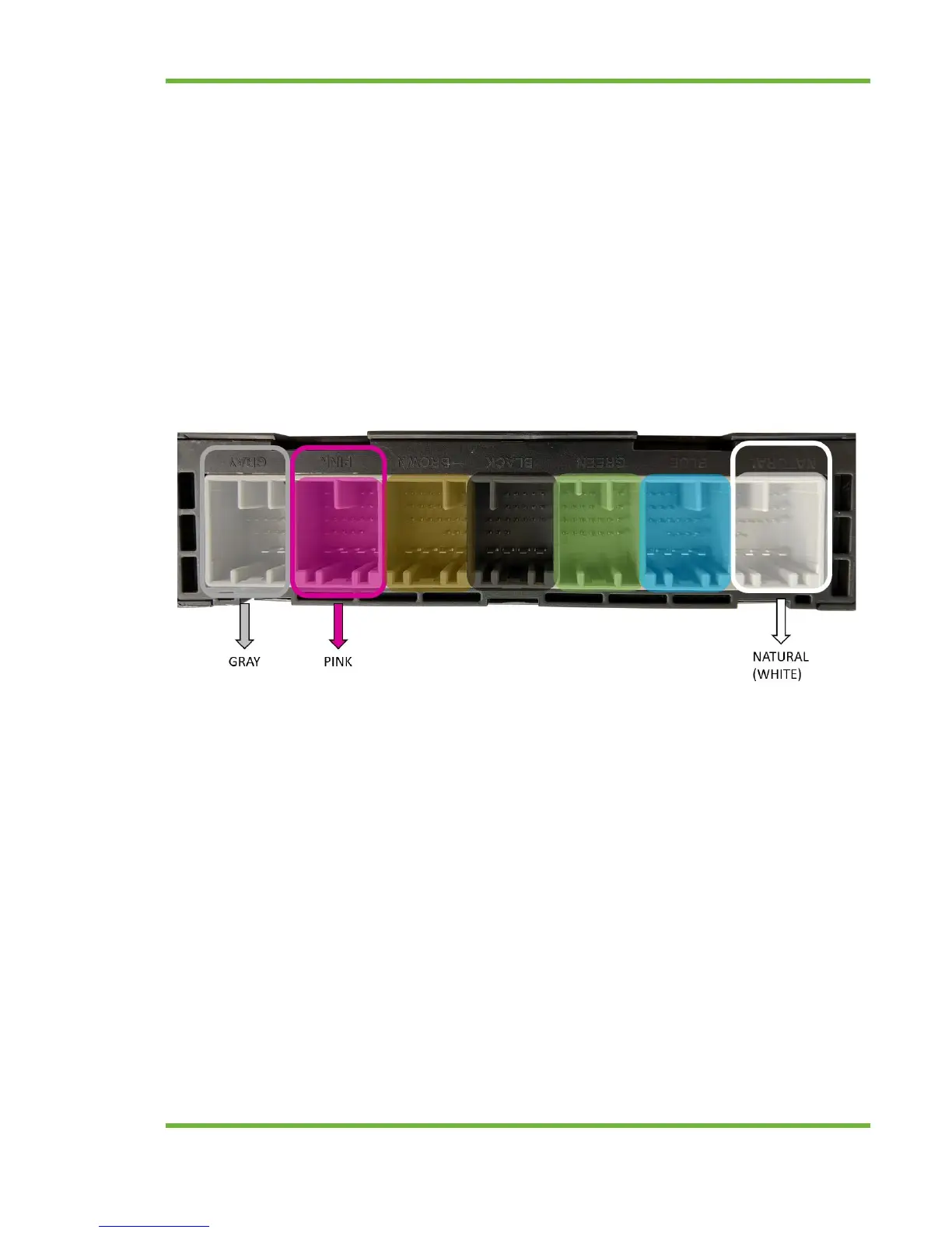
3. Disconnect the natural (white), pink and gray connectors from the body control module
(BCM). The BCM is located under the driver’s side dash behind and above the OBD-II / on
board diagnostic port. It is a rectangular module with seven uniquely colored connectors. To
disconnect depress the connector’s locking tab and pull the connector. See below for image
of the connectors to disconnect. The brown, black, green and light blue connectors should
be left connected. Note that the connector color may vary slightly. Most notably is the pink
connector which appears more purple.
4. Connect the three wire harness connectors previously disconnected from the BCM to the
mating connector of the EFM 3.0 vehicle interface harness. Ensure that the connector colors
are matching (White to white, pink to pink and gray to gray).
5. Connect the three connectors from the EFM 3.0 harness to the BCM. Ensure the connectors
lock into place. The EFM 3.0 vehicle interface harness is intentionally short to keep the
module up and away from the drivers footwell.