Do you have a question about the Spellman XRV225N3000 and is the answer not in the manual?
Responsibility for safe operation, training, monitoring X-ray levels, and using measuring devices.
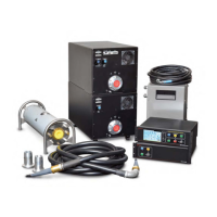
Explains the capabilities and features of the XRV Generator, including its components and connectivity options.
Lists available XRV Generator models with their voltage, power, and polarity specifications.
Details the connectors and layout of the rear panel for the XRV160 generator.
Explains the function of LED indicators on the front panel for status and fault monitoring.
Describes the front panel LED indicators for the XRV225 generator, similar to the XRV160.
Details the connectors and layout of the rear panel for the XRV225 generator.
Describes the rear panel connectors for bipolar XRV320 and XRV350 generators.
Explains the front panel indicators for the cathode generator of XRV320/350 models.
Details the rear panel connectors for the XRV450 generator, designed for bipolar tubes.
Describes the front panel indicators for the cathode generator of the XRV450 model.
Details the front panel components and indicators of the XRVC Controller.
Illustrates and labels the rear panel connectors and ports of the XRVC Controller.
Illustrates and describes spring-loaded HV cables and their connectors.
Shows a basic system diagram for a unipolar setup.
Illustrates a unipolar system including controller and I/O box.
Shows a basic system diagram for a bipolar setup.
Illustrates a bipolar system including controller and I/O box.
Provides general advice on locating the generator, clearance, and environmental considerations.
Explains the procedure for properly grounding all subsystem components.
Illustrates grounding connections for both unipolar and bipolar systems.
| Output Voltage | 0 to 225kV |
|---|---|
| Output Power | 3000W |
| Ripple | 0.1% |
| Voltage Accuracy | 0.1% |
| Operating Temperature | 0°C to +40°C |
| Cooling | Air Cooled |