EasyManua.ls Logo

Sperre HV1/140A User Manual

Default Icon
26 pages
To Next Page IconTo Next Page
Page #1 background imageLoading...
Page #1 background image
Sperre Air Compressor
Two stage, water cooled
Model: HV1/140A
TABLE OF CONTENTS
1. ORDERING REPLACEMENT PARTS .........................................................................................2
2. DESCRIPTION OF COMPRESSOR............................................................................................3
2.1. Design................................................................................................................................... 3
2.2. Safety equipment .................................................................................................................. 3
3. INSTALLATION AND OPERATION .............................................................................................4
3.1. Installation instructions.......................................................................................................... 4
3.2. Cooling water system............................................................................................................ 4
3.3. Starting up............................................................................................................................. 4
3.4. Operation .............................................................................................................................. 5
3.5. Stopping................................................................................................................................5
4. FAULT TRACING .........................................................................................................................6
5. INSPECTION AND MAINTENANCE............................................................................................8
5.1 Maintenance schedule........................................................................................................... 8
5.2. Valves ................................................................................................................................... 9
5.3. Lubricating oil system ......................................................................................................... 10
5.4. Bearings.............................................................................................................................. 10
5.5. Piston and piston rings........................................................................................................ 11
5.6. Flexible coupling ................................................................................................................. 11
5.7. Coolers................................................................................................................................ 11
5.8. Filter .................................................................................................................................... 11
6. ILLUSTRATIONS .......................................................................................................................12
7. TECHNICAL DATA.....................................................................................................................15
8. REPLACEMENT PARTS LIST...................................................................................................18
9. ILLUSTRATIONS FOR REPLACEMENT PARTS LIST.............................................................22
1/26
Question and Answer IconNeed help?

Do you have a question about the Sperre HV1/140A and is the answer not in the manual?

Sperre HV1/140A Specifications

General IconGeneral
BrandSperre
ModelHV1/140A
CategoryAir Compressor
LanguageEnglish

Summary

Ordering Replacement Parts

Description of Compressor

2.1. Design

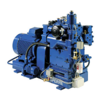
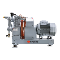
Details the single cylinder, 2-stage, single-acting, water-cooled air compressor design principles and components.

2.2. Safety Equipment

Describes the compressor's safety features including safety valves, safety plates, and automatic control systems.

Installation and Operation

3.1. Installation Instructions

Provides guidelines for compressor unit installation, alignment, and piping recommendations for optimal performance.

3.2. Cooling Water System

Emphasizes the critical role of a reliable cooling water supply and proper temperature monitoring for compressor longevity.

3.3. Starting Up

Outlines essential pre-start checks and procedures, including oil level verification, valve lubrication, and system readiness.

3.4. Operation

Details normal operating parameters, monitoring requirements, and procedures for draining condensed moisture during operation.

3.5. Stopping

Covers manual procedures for short-period stopping and long-period shutdown, including preservation measures.

Fault Tracing

Compressor Capacity Issues

Lists common causes and remedies for low compressor capacity or failure to supply full pressure.

LP Safety Valve Blows

Explains potential causes for the LP safety valve blowing and the necessary corrective actions.

HP Safety Valve Blows

Discusses reasons for the HP safety valve blowing and the required maintenance or replacement steps.

Frequent HP/LP Valve Maintenance

Addresses causes for HP and LP valves requiring frequent maintenance and provides solutions for reliability.

Crankcase Overheating or Knocking

Identifies issues leading to overheating or knocking sounds in the crankcase and suggests appropriate remedies.

Piston Overheating and Scoring

Details the causes of piston overheating and scoring, along with corrective measures for piston and bearing issues.

Excessive Lube Oil Consumption

Explains the reasons behind excessive lube oil consumption and outlines the steps for diagnosis and correction.

Excessive Moisture in Air Lines

Addresses the problem of excess moisture in air delivery lines or cylinders, identifying causes and fixes.

Water Jacket Safety Valve/Bursting Disc

Covers scenarios where the water jacket safety valve or bursting disc blows and their respective remedies.

Inspection and Maintenance

5.1 Maintenance Schedule

Provides a comprehensive schedule for daily, 500, 1000, 3000, 9000, and 12000-hour maintenance tasks.

5.2 Valves

Details the procedures for overhaul and maintenance of compressor valves, including cleaning, inspection, and part replacement.

5.3 Lubricating Oil System

Explains the lubricating oil system's operation, pump function, and lists recommended synthetic lubricants for the compressor.

5.4 Bearings

Describes the compressor's big-end plain bearings and crankshaft ball bearings, including fitting and clearance specifications.

5.5 Piston and Piston Rings

Covers the step-by-step process for dismantling and reassembling the piston and piston rings for maintenance.

5.6 Flexible Coupling

Details the procedures for dismantling, reassembling, and accurately aligning the flexible coupling between components.

5.7 Coolers

Highlights the importance of maintaining clean LP and HP coolers free from deposits to ensure efficient and reliable compressor operation.

5.8 Filter

Describes the recommended cleaning procedures for both the air filter and the oil filter to maintain performance.

Illustrations

Technical Data

T1 Coolant Flow

Presents data on the compressor's shaft speed in rpm and coolant flow rate in liters per minute.

T2 Recommended Pressures and Temperatures

Lists recommended operating pressures and temperatures for cooling water, lubricating oil, and air systems.

T3 Torque Table

Provides a table specifying torque values in kpm and Nm for various compressor components based on size.

T4 Clearances

Details essential clearances and lifting heights for valve components, pistons, cylinders, and bearings.

T5 General Data

Offers general specifications including cylinder and crankshaft diameters, stroke, and oil capacity of the compressor.

T6 Air Compressor Data

Lists key compressor data such as type, capacity, revolutions, power requirement, and working pressure.

Replacement Parts List

Illustrations for Replacement Parts List

Related product manuals