PA100W RF Power Amplifier
3. PA100W RF Module with De-blanking Circuitry
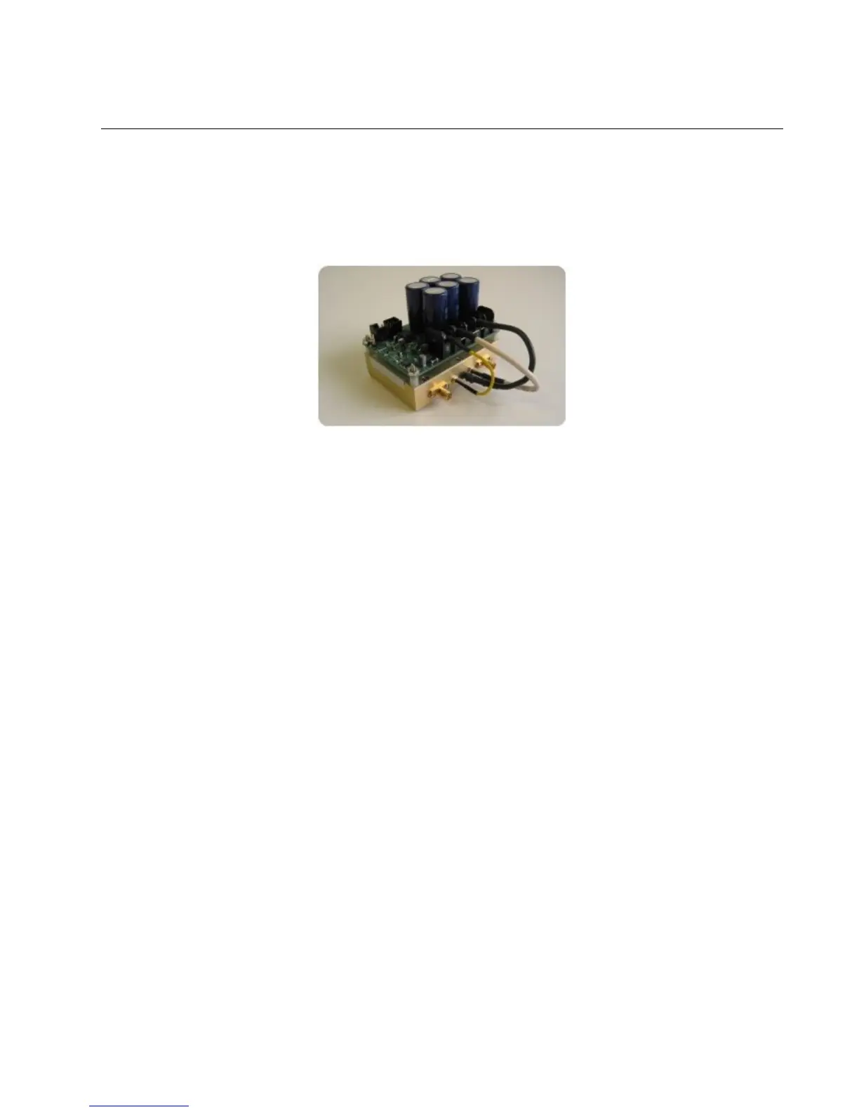
This configuration does not have any enclosure for the PA100W RF module. It includes the de-
blanking circuitry mounted on top of the power amplifier to enable it when a TTL pulse is applied to
the control input pin. The module with no enclosure is shown below in Figure 1.
Figure 1: PA100W RF power amplifier module – no
enclosure.
RF Input and Output Connectors
When connecting the PA100W RF power amplifier module, the RF signal source should be
connected to the SMA jack on the left hand side (top view) of the circuit (RF in). The SMA jack on
the right hand side (top view) is the RF output from the power amplifier (RF out). See Figure 2, on
the next page, for details.
http://www.spincore.com 7 2012-09-21