PA100W RF Power Amplifier
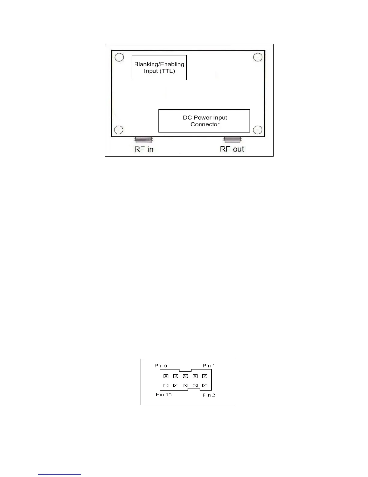
Figure 2: Top view of the PA100W power amplifier module depicting
connectors. RF in and RF out are SMA jack connectors, Input TTL is an
IDC connector and the input DC power connector is a screw terminal
block.
TTL Control Input Connector
The PA100W power amplifier module has a 10-pin shrouded male IDC connector, pin diagram
shown in Figure 3, which supplies the input TTL control signal. The control signal is pin 8 on the IDC
header and the corresponding ground is pin 7. The input is terminated by a 100-ohm load and
requires an external source capable of outputting at least 10 mA. The TTL requirements for the
deblanking control input are standard low voltage TTL values of 3.3V for a logical high, 0V for
logical low. A logical high signal is required to deblank (enable) the PA100W. In testing, the TTL
deblanking pulse is typically applied 300 us prior to the application of the RF pulse. The end of the
deblanking signal coincides with the end of the RF pulse. See Figure 3 below for details.
Figure 3: 10-pin IDC connector (Digi-Key part A33159-
ND). Mates with Digi-Key part HKC10H-ND or similar.
http://www.spincore.com 8 2012-09-21