15
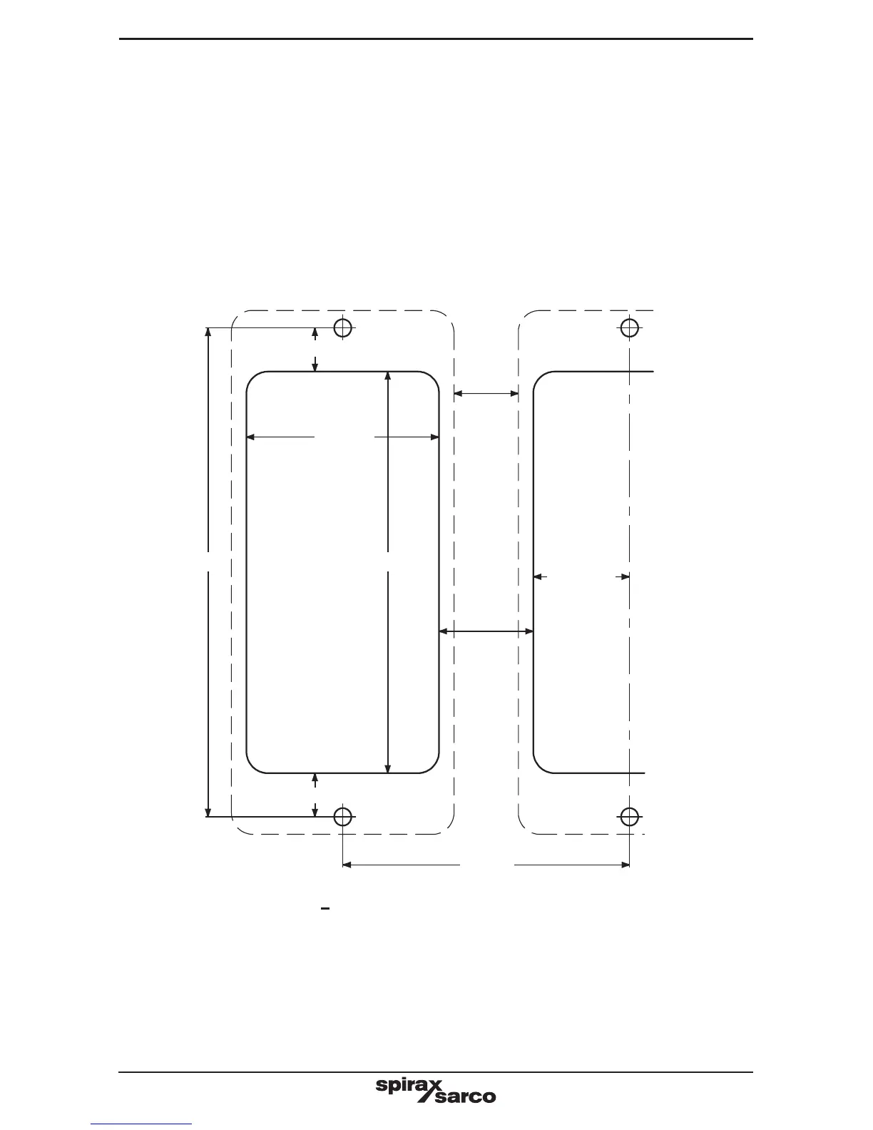
Fig. 5 Chassis plate / panel - cutout diagram
Fixing template cutout notes:
- Solid line indicates cutout required for panel mounting.
- Broken line indicates product outline.
- A minimum gap of 15 mm between units must be provided for product cooling.
- Mounting hole dimensions are the same for both panel and wall mounting.
112 mm
67 mm
10 mm
45 mm
92 mm
22 mm
22.5 mm
Ø 4.2 mm
Ø 4.2 mm
15 mm
Ø 4.2 mm
Ø 4.2 mm
10 mm
- Cut the panel to the dimensions given in Figure 5. Drill the screw holes in the panel in the
positions indicated.
- Remove the backing from the gasket supplied and apply to front face of the product.
- The bezel can be used to enhance the appearance of the panel cutout. If required, fit this
to the outside of the panel.
- Fit the unit from the rear of the panel, and secure using the screws, washers (and bezel)
provided.
- Tighten the M4 screws to 1.0 - 1.2 Nm.
WARNING: Do not drill the product case or use self-tapping screws.
 Loading...