IM-P402-44 AB Issue 15
17
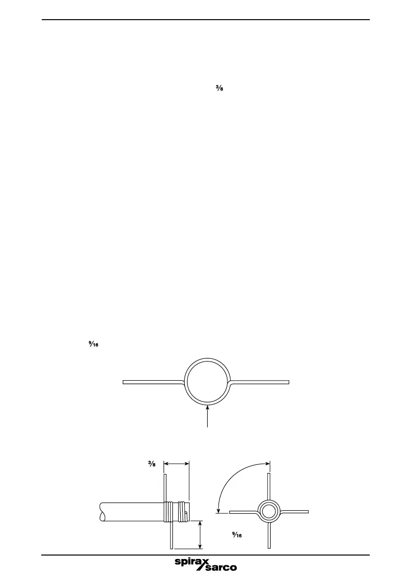
Pinchtogether(torelaxcoil)
for fitting to probe tip
Maximum 10 mm (
")
90°
14 mm (
")
End view
Side view
Fig. 13
Fig. 14
5.2 Test method
1. Drain water level to at least 50 mm (2") below alarm level and vent boiler or vessel to
atmosphere.
2. Remove probe (if installed) and fit a pair of checking wires to the end of the probe tip, 90°
relative to each other and a maximum 10 mm (
") from the tip end - see Figures 13 and 14.
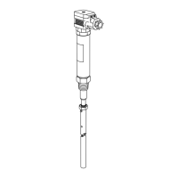
3. Carefully pass probe through screwed connection and into the protection tube. The checking
wires will deflect to allow them to pass through, and then spring back to their original positions.
4. Screw down probe by hand, without using PTFE tape.
5. Attach the earth lead of the meter to the boiler and the live lead to pin 1 of the probe connector.
Check the contact to boiler with the meter.
6. Activate meter and observe display. Slowly unscrew probe one full turn (without unduly
rocking the probe).
7. If no short circuit is found, disconnect the meter leads, unscrew and withdraw the probe,
taking care not to catch the checking wires on the underside of the screwed connection.
8. Remove checking wires and install probe as described in Section 3, 'Installation'.
9. Low alarms must be functionally tested by lowering the water level before the boiler is allowed
to run unsupervised.
Separate literature describes this procedure.
10. Complete the clearance record sheet (see page 18 and 19).
WARNING: It is essential to remove the checking wires from the probe before
commissioning the boiler or vessel. Failure to do this could lead to the low alarms not
working.
If a short circuit was found during the test then further investigation is needed. Some possible
reasons are listed below:
- Probe tip bent or not attached properly.
- Protection tube and /or screwed connection out of alignment.
- Protection tube not of large enough bore and/or not deep enough (the tube should be at least
40 mm (1
") deeper internally than the end of the probe, see Figure 12).