Do you have a question about the Spireon GoldStar ATS300 and is the answer not in the manual?
Lists the components included in the Spireon-supplied tracking device kit.
Lists the components included in the optional magnetic mounting plate kit.
Lists the tools and materials that the customer must supply for installation.
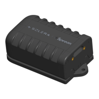
Illustrates the top front view of the tracking device, highlighting key components.
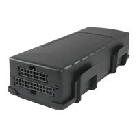
Illustrates the bottom rear view of the tracking device, highlighting key components.
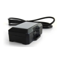
Instructions on how to power on the tracking device using the power-up button.
Explains the meaning and actions of the red and green LED indicators.
Provides examples of suitable high-mounting locations within a vehicle.
Details the procedure for mounting the device using zip ties.
Explains cleaning and applying VHB tape to the device for mounting.
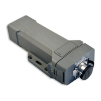
Attaches the magnetic mounting plate to the device using M3 x 6 screws.
Attaches the magnetic mounting plate to the device using M3 x 6 screws.
Automatically activated when the Tracking Device powers on.
Activated after establishing home and work profiles.
Manually activated by user for live trip tracking.
The GoldStar ATS300 is a battery-operated tracking device designed for covert installation and operation in vehicles. This compact device provides location tracking and reporting capabilities, making it suitable for various applications, including asset management and recovery.
The primary function of the GoldStar ATS300 is to track the location of a vehicle using GPS and cellular networks. It operates in several modes to optimize battery life and tracking frequency based on specific needs. The device is equipped with LED indicators to provide visual feedback on its operational status, including GPS acquisition and cellular connection. An optical tamper sensor is integrated into the device to detect unauthorized removal or tampering, enhancing security.
Powering Up: To power up the ATS300, users must locate the power-up button on the flat face of the device. Using the provided power-up tool, the button needs to be pressed and held for 5 seconds. Upon successful power-up, a red LED will flash for 5 seconds, indicating activation.
LED Indicators: The device features two LED indicators:
Mounting Locations: For optimal performance, the ATS300 should be mounted as high as possible within the vehicle, with the LEDs facing upwards towards the roof. Recommended mounting locations include behind the knee bolster, behind the glove box, or under the rear deck above the metal support structure. It is crucial to avoid mounting the device below any metal obstructions or near moving parts such as the steering shaft, tilt column, or pedals, as this can interfere with its operation and potentially cause damage.
Optical Tamper Sensor: The device includes an optical tamper sensor on its bottom surface. During installation, it is essential to ensure that the mounting location allows the sensor to be covered. If the chosen location does not naturally cover the sensor, black tape should be placed over it to prevent invalid tamper alerts, which could otherwise trigger unnecessary notifications.
Installation Options: The GoldStar ATS300 offers four distinct installation methods to accommodate various vehicle types and user preferences:
Zip Tie Mounting:
VHB Adhesive Mounting:
Screw Mounting (requires optional Magnetic Mounting Plate):
Magnetic Mounting (requires optional Magnetic Mounting Plate):
Device Behavior - Mode Definition: The ATS300 operates in three distinct modes, each with a specific purpose:
Quick Track:
Daily Track:
Recovery Track:
The manual emphasizes reading the entire guide before installation, suggesting that proper initial setup is key to device longevity and performance. While explicit maintenance features are not detailed, the design choices imply certain aspects:
| Connectivity | Cellular |
|---|---|
| Water Resistance | IP67 |
| GPS Accuracy | 2.5 meters |
| GPS Technology | GPS/GLONASS |
| Cellular Technology | 4G LTE |
| Device Type | GPS Tracker |