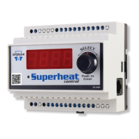
INSTALLATION
When handling the boards, electrostatic protection proce-
dures should be followed. The installer should be ground-
ed through a ground strap. If ground straps or other ESD
protection is not available, handle the board only by the
edges of the board. Another safe place to hold the board
is by the battery holders. DO NOT TOUCH ANY COM-
PONENTS ON THE BOARD EXCEPT THE BATTERY
HOLDER OR RELAYS.
1) The board should be mounted in a dry, protected environ-
ment using the mounting holes in each corner. Make sure
none of the printed circuit paths or components are touching
the metal panel or any conductive material.
2) If only one valve is used, connections are to be made to ter-
minal block closest to display readout and push buttons PB1
and PB2.
3) Controllers are configured for pressure temperature
superheat .
4) Connect temperature sensor to TS2. The sensor is not
polarized. With the clamps furnished, the sensor should be
mounted to the suction line after the evaporator.
5) The pressure transducer should be mounted on the suction
line near the temperature sensor location. The transducer con-
nections to the board are shown:
The power wire is red and is connected to the 1+ terminal
The signal wire is green and is connected to the 1S terminal
The ground wire is black and is connected the 1- terminal
6) DI1 is a digital input used as a pumpdown terminal. A
short or closed contact from an external relay will close the
valve for pumpdown. When the relay opens or the short is
removed, the valve will return to normal operation.
7) Power is connected to the terminal marked 24VAC. Power
requirements are 24 volts AC at 40 VA. For protection from
electrical transients, connect one MOV varistor between one
leg of the input voltage of the 24 VAC transformer and earth
ground. Connect a second MOV varistor between the other
leg of the input voltage of the 24 VAC transformer to earth
ground. A recommended part number for a MOV is Harris
Semiconductor part number V150LA20A for 120 VAC input,
or part number V275LA20A for 208/240 VAC input.
OPERATION
When first powered up the numeric display will show actual
superheat.
1) The small Green LED will be lit.
2) PB2 will toggle the readings as follows and the small
Green LED will be steady or flash:
• Actual Superheat, LED constant.
•Valve percentage open, LED slow flash.
3) To change set point for superheat:
• Make sure the display shows the superheat.
• Press and hold PB1 and PB2 for 8 seconds, LED will
flash rapidly.
• Use PB1 to increment set point.
• Use PB2 to decrement set point.
• Press and hold PB1 and PB2 for 5 seconds to lock in
set point and return to actual superheat.
4) To manually change valve position, scroll to valve position
reading with PB2.
• Press and hold PB1 and PB2 simultaneously for 8
seconds, Green LED will flash rapidly.
• Increment "valve open" percentage by pressing PB1
for 1 second.
• Decrement "valve open" percentage by pressing PB2
for 1 second.
•Valve will maintain manual open position for 1 hour or
until PB1 and PB2 are pressed simultaneously and
held for 5 seconds.
REMOTE PANEL DISPLAY
A remote panel display is available that will allow access to
all the parameters that the controller uses. The Remote Panel
Display can be used as a set point tool in production, a diag-
nostic tool in the field or as a permanent readout device on the
controller. A five foot cable is included.
Plug the remote display into the telephone jack (J9) on the
controller. The following is a list of readings available.
SUPH - Superheat read by controller
POSN - Number of steps valve is open (0-1596, 0-3192
or 0-6386)
PRES - Pressure read by the transducer (0-153 psi
absolute or gauge)
TEMP -Temperature read by the temperature sensor (-40
to 102°F)
TSAT -Saturated temperature calculated from pressure.
ACON, PMDN - ACON when in normal operation, PMDN when
in pumpdown
R22, 134A, 407C,
404A, R507 - R22 for regfrigerant R22, 134A for refrigerant
R134a, 407C for refrigerant R407C, 404A for
refrigerant R404A, and R 507 for refrigerant
R507.
LRGE, SMAL,
MEDM -LRGE if the EEV used is an SEI-50 or larger.
SMAL if the EEV used is smaller than an SEI-25.
MEDM if the EEV used is an SEI-25
SHSP - Superheat set point (0 to 16 deg F). Default is 10
deg F.
MOPD - Maximum operation suction pressure set point (0
TO 153 PSI). Default is 153 PSI.
CTSP - Cut out suction pressure set point (0 TO 153 PSI)
CALP - Calibrate pressure transducer
CALT - Calibrate temperature sensor
PROP -Proportional gain set point. Number of steps per
degree that superheat is above or below the super-
heat set point (5 to 255 steps per degree). Default
is 45.
INTG - Integral set point. Number of seconds the con-
troller waits to update the reference valve posi-
tion. (1 to 120 seconds). Default is 10 seconds.
PANEL DISPLAY
 Loading...