This document describes the SPRSUN Monoblock DC Inverter Series, an air source swimming pool heat pump designed for both heating and cooling.
Function Description
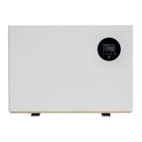
The SPRSUN Monoblock DC Inverter Series is an air source heat pump specifically designed for swimming pools, offering both heating and cooling functionalities. It utilizes a DC inverter system for efficient operation. The unit is controlled via an LED color screen line controller and can also be managed remotely through a Wi-Fi module and a dedicated mobile application ("Smart Life").
Important Technical Specifications
Electrical Connections:
- Single-phase models (CGY015V3 to CGY060V3):
- Voltage: 220V~240V/50Hz or 60Hz/1Ph
- Connecting terminal: L, N, Ground
- Max. Current (A) and Line (mm²):
- CGY015V3: 2.5 mm², 6.5 A
- CGY020V3: 2.5 mm², 8.3 A
- CGY025V3: 2.5 mm², 9.8 A
- CGY030V3: 2.5 mm², 13.1 A
- CGY035V3: 4.0 mm², 16.2 A
- CGY040V3: 4.0 mm², 21.8 A
- CGY050V3: 6.0 mm², 26 A
- CGY060V3: 6.0 mm², 29.9 A
- Three-phase models (CGY-050V3 to CGY-080V3):
- Voltage: 380V~420V/50Hz or 60Hz/3Ph
- Connecting terminal: L1, L2, L3, N, Ground
- Max. Current (A) and Line (mm²):
- CGY-050V3: 4.0 mm², 11.48 A
- CGY-060V3: 4.0 mm², 13.2 A
- CGY-080V3: 4.0 mm², 17.1 A
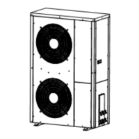
Internal Components (Refer to diagram):
- Chassis
- Titanium tube heat exchanger
- DC compressor
- Middle diaphragm
- Rear service panel
- Power inlet hole
- Pressure gauge
- Air outlet network
- Air outlet frame
- Wind leaf
- DC motor
- Fan support
- Finned evaporator
- Electrical box
- Frequency converter
- Evaporator cover plate
- Cover
- Cover plate of electrical box
- Front panel
- Control panel
- Electronic expansion valve
- Four way valve
Queryable Parameters (via controller):
- A01: Inlet water temperature (-30~99°C)
- A02: Outlet temperature (-30~99°C)
- A03: Ambient temperature (-30~99°C)
- A04: Exhaust gas temperature (0~125°C)
- A05: Return air temperature (-30~99°C)
- A06: Outer coil temperature (-30~99°C)
- A07: Inner coil temperature (-30~99°C)
- A08: Main expansion valve opening
- A09: Enthalpy expansion valve opening
- A10: Compressor current
- A11: Heat sink temperature
- A12: DC bus voltage value
- A13: Actual speed of compressor
- A14: DC fan 1 speed
- A15: DC fan 2 speed
Usage Features
Installation Guidelines:
- Must be installed in an open space, typically on a house roof.
- Should be placed in a dry, well-ventilated environment to prevent corrosion or short circuits of electronic components.
- Avoid installation in corrosive, volatile, or flammable liquid/gas environments.
- Due to noise, avoid installation near bedrooms, living rooms, or meeting rooms.
- The bottom of the heat pump should be at least 50cm higher than the ground to prevent rain or snow ingress. Can be installed on concrete basic or steel support.
- A shed is recommended to protect the unit from rain and snow, which can reduce shell lifetime and block the air outlet.
- A water drainage ditch should be set around the heat pump for condensing water and defrosting water.
- Keep the heat pump far from kitchen exhaust to prevent oil accumulation on finned tubes.
- Install on flat concrete blocks or a raised concrete platform/steel bracket.
- Use 4pcs anti-shock pads between the heat pump and the base/bracket.
- Check heat pump dimensions before making the base/bracket.
- Confirm heat pump direction according to project design before fixing.
- Use expansion bolts to fix the heat pump to a concrete base.
- Circulating water pipe must be PVC50.
- Water temperature sensors should not directly touch water; use a sensor tube.
Controller Operation:
- Power Button (⏻):
- Short press: Exit key, return to main page.
- Long press (3 seconds): Turn on/off the unit from the main interface.
- Mode Key (M):
- Long press (3 seconds in power-on state): Switch between heating mode and cooling mode.
- Plus Key (△):
- Single press (in main interface, power-on): Adjust the current mode setting temperature upwards.
- Minus Key (▽):
- Single press (in main interface, power-on): Adjust the current mode setting temperature downwards.
- Long press (3 seconds in main interface): Enter unit status parameter query. Use △ and ▽ to scroll. Press ⏻ to exit.
- Setting Key (⏴):
- Long press (3 seconds): Enter clock setting state.
- Hour digit flashes: Adjust hour with △ and ▽.
- Press ⏴ again: Minute digit flashes. Adjust minute with △ and ▽.
- Press ⏴ again: Exit.
- Long press (3 seconds): Enter timing setting.
- "Time On 1" appears, "Hour" flashes. Set hours with △ and ▽.
- Press ⏴: Switch to "minutes". Set minutes with △ and ▽.
- Press ⏴: Switch to "timing off 1". Repeat setting hours and minutes.
- Press ⏻ to exit/confirm.
- To cancel timer setting, set power-on and power-off times to be the same.
- Forced Defrosting: Press M and ⏴ simultaneously. Flashing display indicates defrosting.
- Frequency Mode Switching: Press ⏻ in the boot interface to switch between silent, smart, and strong modes.
- Celsius/Fahrenheit Switch: Long press ⏻ and M simultaneously for 3 seconds in shutdown state to switch units.
- Unlock/Lock Screen: Press and hold △ and ▽ simultaneously for 3 seconds.
- Manual Electric Heating: Long press ⏴ for 3 seconds to manually turn on/off electric heating.
Wi-Fi Module Networking (via "Smart Life" APP):
- APP Download & Install: Scan QR code (Android/iOS) to download "Smart Life" app.
- Start APP: Click the "Smart Life" icon on the desktop.
- Register & Login:
- Register: Click "Register", agree to privacy policy, enter mobile number, get verification code, set password, complete.
- Family Setup (after registration): Create a family, add family members, set family name, add rooms, complete.
- Login: Enter account details directly.
- Forgot Password: Choose authentication number to login.
- Wi-Fi Module Networking:
- Step 1 (Heat Pump): Within 10 seconds of power-on, press and hold "switch", "△", and "timing" buttons simultaneously for 5 seconds to enter smart distribution grid mode. The Wi-Fi icon will flash quickly. (Unit exits distribution grid mode after 3 minutes if not connected; re-press "switch", "△", "Timed" for 5 seconds to re-enter).
- Step 2 (APP): Open "Smart Life", click "+" or "Add Device", select "Air Condition" under "Household Power" to enter "Add Device" interface.
- Step 3 (APP): Confirm the line controller's Wi-Fi icon is flashing, then click "Confirm indicator is flashing". Enter the Wi-Fi password (must be 2.4G Wi-Fi and match phone's connection), click "Confirm".
- Step 4 (APP): After "found device", "Device register to Smart Cloud", "Device initialize" are complete, "Add device successfully" will appear. You can change the device name and location, then click "finish" to enter the operation interface.
APP Operation Instructions:
- Main Interface: Displays current water tank temperature, set temperature, error information, current mode.
- Cooling/Heating Set Temperature: Adjust by rotating the white circle (counter-clockwise to reduce, clockwise to increase).
- Mode Switching: Click "Heating Mode" to select cooling, heating, water mode, water+heating, water+cooling.
- Open Key (Power button): Click to turn on/off.
- Timing: Click to add timing off/on time.
- More: Access device name change, installation location, network status, shared users, device groups, device information.
- Modify Device Name: Go to "More" -> "Device Information" -> "Device Name" to rename.
- Device Sharing:
- Click "Add Sharing" in the "Share Device" section.
- Enter the account of the person to share with.
- The shared person will see the device in their "Sharing Invitations" and can operate it.
- To delete a shared person, press and hold their name in the list and click "Delete".
- Timer Setting: Click the timer icon on the main interface, then "Add Schedule". Slide to set hours/minutes, repetition week, and turn on/off status. Save using the top right corner.
Maintenance Features
Troubleshooting Guide:
- Heat pump doesn't run:
- Possible reason: Power supply cable is loose, fuse of power supply is fused.
- Method: Cut off power, check/repair cable. Change fuse.
- Heating capacity is too small:
- Possible reason: Refrigerant not enough, water system insulation not good, air heat exchanger dirty, water heat exchanger scaled.
- Method: Check for leakage, repair, refill gas. Improve insulation. Clean air heat exchanger. Clean water heat exchanger.
- Compressor doesn't run:
- Possible reason: Power supply error, cable connecting is loose, compressor is overheat.
- Method: Check reason, solve. Check/repair loose cable. Check reason, repair.
- Compressor noise is loud:
- Possible reason: Expansion valve damaged leading to liquid entering compressor, internal parts of compressor damaged, compressor lack of oil.
- Method: Change expansion valve. Change compressor. Compensate oil for compressor.
- Fan motor doesn't run:
- Possible reason: Fan blade fixing screw is loose, fan motor damaged, fan motor capacitance damaged.
- Method: Tighten screw. Change fan motor. Change capacitance.
- Compressor run, but not heat:
- Possible reason: No refrigerant at all, compressor damaged.
- Method: Check for leakage, repair. Change compressor.
Remote Control Removal:
- Smart Distribution Network Mode: Long press △ and M simultaneously for 5 seconds. The unit will re-enter smart distribution network mode (Wi-Fi icon flashes for 3 minutes). If not re-configured, it will quit.
- AP Distribution Mode: Press and hold ▽ and M simultaneously for 5 seconds. The unit will re-enter AP distribution mode.
Remove APP:
- From the device operation main interface, click "More" -> "Enter the device details interface".
- Click "Remove Device".
- The Wi-Fi icon will stop flashing, and the network connection will be quit after 3 minutes if not re-configured.
Warranty Information:
- Terms: Warranty covers quality issues.
- Repair: Present warranty card and invoice/proof for repairs.
- Exclusions: No warranty for re-fitment, adding functions, invalid warranty card/proof, lack of proof, incorrect operation, damage by non-professionals, moving/falling, natural disaster, or freezing due to undischarged water after power failure.
- Record: A warranty card is provided to record repair dates and details.