Assembly & Operating Instructions Form No. 102472
ASSEMBLY
Sheet No. 2 of 4
Rev. Date: 25 May 1994
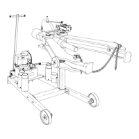
See Figure 1:
1. Position the left leg (60925) and the right leg (60926)
as shown. Set the pump mounting plate (60937) over
the correct holes and bolt loosely.
2. Position the upright (60924) as shown and bolt
loosely. Carefully measure from the end of each leg
to the cross tube. Make any adjustment needed to
equalize the measurements. Securely tighten the
four bolts holding the upright. Securely tighten the
four bolts holding the pump mounting plate to the
legs.
3. Mount and fasten the 8” wheels onto the frame in the
parts sequence shown.
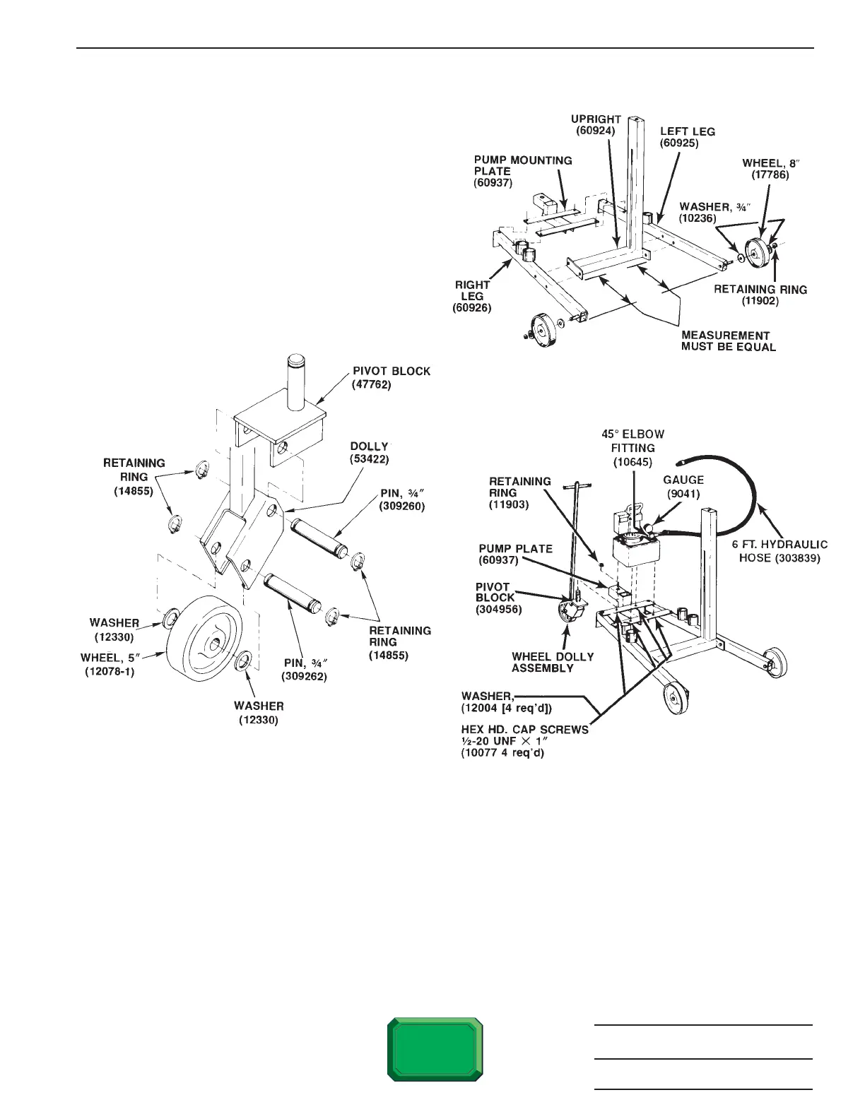
See Figure 2:
4. Assemble the wheel dolly as shown.
See Figure 3:
5. Fasten the wheel dolly to the leg assembly.
6. Using hex head cap screws and washers, attach the pump to the pump mounting plate as shown.
7. Remove the pipe plug from the pump gauge port. Thread the 45° elbow fitting into the gauge port, angled upward
to make room for the gauge.
Note: Seal all hydraulic connections with Power Team HTS6 thread sealant. Teflon tape can be used if only
one layer of tape is used. Apply carefully, two threads back, to prevent the tape from being pinched by the
coupler and broken off inside the pipe end. Loose pieces of tape can travel through the system and obstruct
the flow of oil or cause jamming of precision parts.
8. Install the pressure gauge on the 45° elbow fitting. Turn the face of the gauge so it can be read when standing to
the right rear of the puller.
9. Assemble the hose half coupler on the hose. Thread the other end of the hose into the pump outlet pump.
 Loading...