Assembly & Operating Instructions, Form No. 102472, Back sheet 2 of 4
See Figure 4:
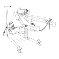
10. Clean and lubricate the threads on the ram body and head
assembly. Thread the ram into the head assembly as shown.
WARNING: To help prevent personal injury, the ram must be
fully threaded into the puller head until threads are visible on the
opposite side of the puller head block.
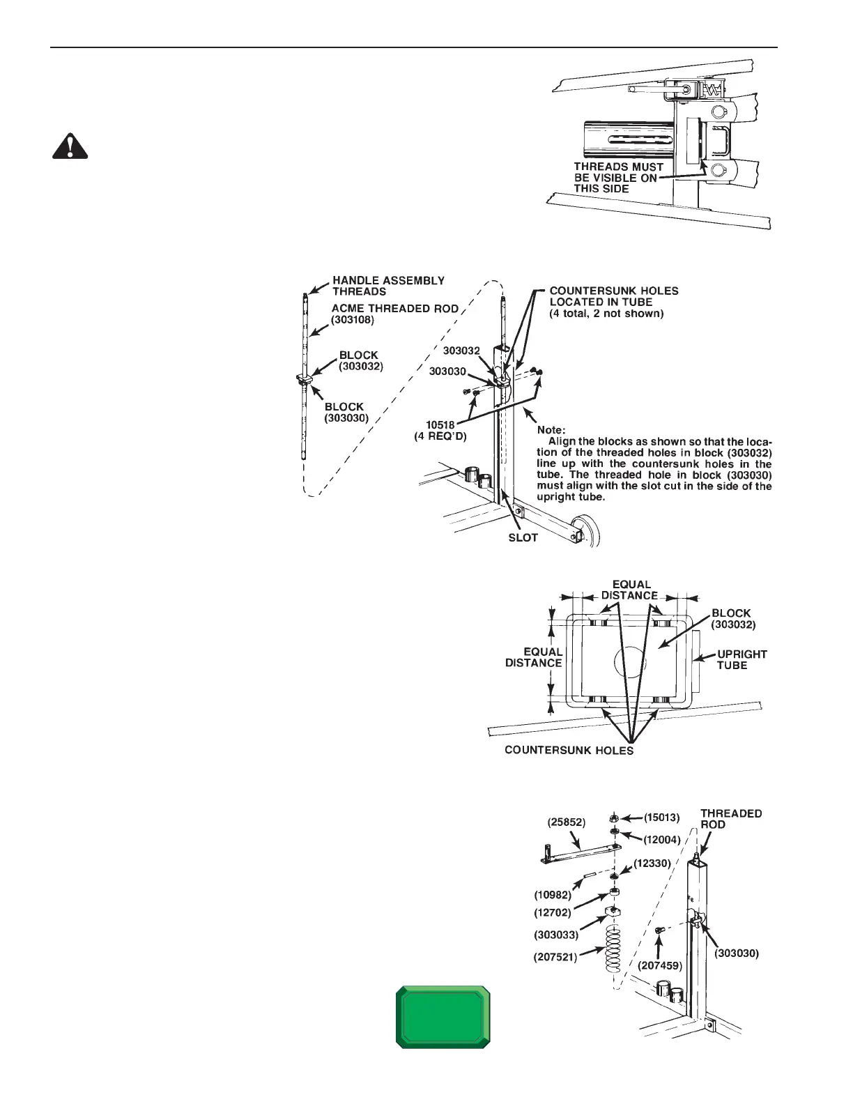
See Figure 5:
11. Grease the threads on the
acme threaded rod (303108).
Grease both slotted sides on
the inside of the upright tube.
12. Thread the block (303030)
about half-way down the
threaded rod.
13. Slip the block (303032) over
the threaded rod from the
end that has been designated
as the handle assembly end.
Position the blocks as shown.
Lower this assembly into the
rectangular tube.
See Figure 6:
14. Align the countersunk holes in the tube with the threaded
holes in the block (303032). Thread four 3/8-16 x 1” lg.
screws (10518) into the block finger-tight.
15. Look down from the top of the tube. Tighten each screw as
needed until the block is centered with each side parallel to
its corresponding side of the tube. The block should be
centered to about 1/16” tolerance.
16. Lower the rod until the threaded holes in the lower block
(303030) are aligned with the slot in the tube. Thread the
hex socket head shoulder screws (207459) into each side of
the block and tighten to 30 ft. lbs.
See Figure 7:
17. Position the threaded rod as shown. Place the 12” spring (207521), the
spring cap (303033), the thrust bearing (12702), and washer (12330)
over the threaded rod.
18. Insert the 1/4” roll pin (10982) into the drilled hole in the threaded rod.
Center the roll pin until about 3/8” of the roll pin is extended on each
side of the rod.
19. Place the entire spring and rod assembly into the tube.
FIGURE 4
FIGURE 5
FIGURE 6
FIGURE 7
 Loading...