Assembly & Operating Instructions Form No. 102472
Sheet No. 3 of 4
Rev. Date: 25 May 1994
See Figure 8:
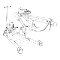
20. Place the puller cart in position to fit the puller jaw head
assembly onto the spring-loaded tube upright. Attach a
crane to the lifting hook located near the head of the
puller jaw head assembly. Lift the entire assembly over
the tube upright.
21. Grease the rollers on the puller jaw and head assembly.
Grease the slotted sides of the upright tube. Lower and
slide the entire head assembly down until it rests evenly
on the shoulder bolts. IMPORTANT: The spring cap
(303033) must slide into the tube upright evenly as
pressure from the weight of the puller head assembly
pushes the spring (207521) down over the threaded
rod (303108). See Figure 9.
22. Refer to Figure 7 again. Assemble the handle (25852),
washer (10204), and nut (15013) onto the end of the
threaded rod as shown.
See Figure 10:
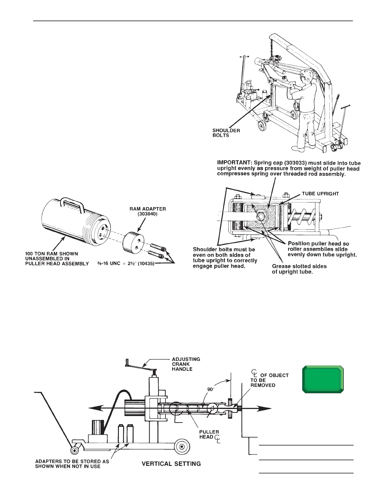
23. Install the ram adapter (303040) on the end of the ram
using two 3/8-16 UNC x 2-1/2” socket head screws
(10435). Tighten securely.
OPERATING INSTRUCTIONS
VERTICAL SET-UP: See Figure 11
The head and pulling jaw assembly on this puller is designed to compensate for some degree of error in a job set-up.
The puller head is spring-loaded, permitting 7° flexibility in upward movement and 3° flexibility in downward
movement. Note: Because of this feature, the head and puller jaw assembly may rest at a slight upward angle.
1. Adjust vertical set-up by using the crank handle shown in Figure 1. The centerline of the object being pulled must
be on the same centerline as the puller head. Note: Because of spring loading, you may have to turn the
crank handle several times before the head starts moving.
2. Align the puller horizontally and vertically as close as possible to the same centerline as the object to be pulled.
The head cannot compensate for poor alignment.
FIGURE 8
FIGURE 10
FIGURE 9
FIGURE 11
 Loading...