Assembly & Operating Instructions, Form No. 102472, Back sheet 3 of 4
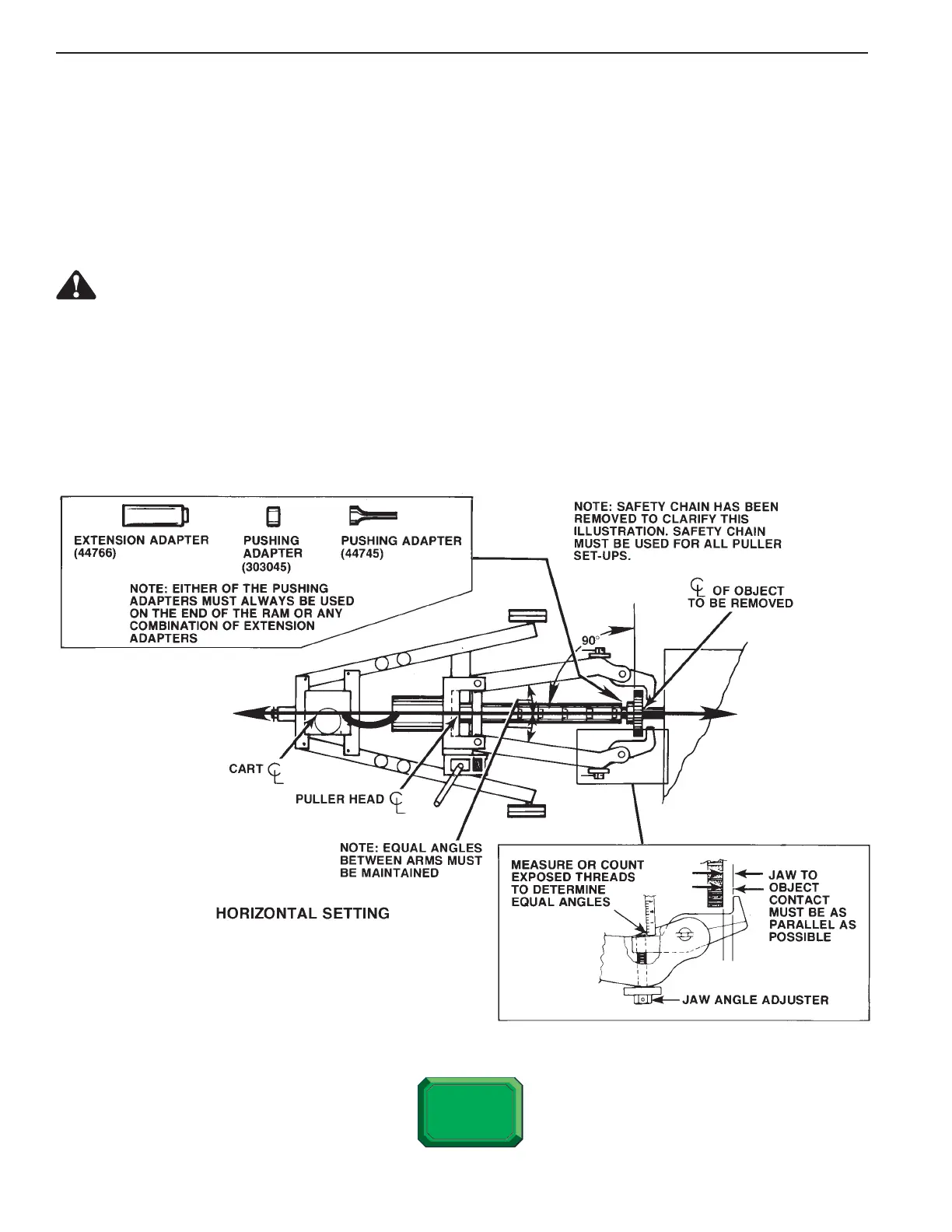
HORIZONTAL SET-UP: See Figure 12
1. Adjust the horizontal by positioning the puller cart as shown in Figure 12. The centerline of the object being
removed must be at a 90° angle to the flat surface of the jaws and on the same centerline as the puller cart and
the puller head.
JAW and ARM ADJUSTMENT: See Figure 12 Inset
WARNING: To help prevent personal injury, do NOT apply hydraulic pressure to the object being
pulled until the angles of the jaws are set equally.
1. Move the puller arms inward to a minimum width of 15” or outward to a maximum width of 48”. In all adjustments
with the arms, maintain equal angles between the arms as shown in the Figure 12 inset. Note: If the jaw contact
area is flat and even on the object being pulled, an equal amount of threads visible on each screw shaft
would indicate an equal angle between both arms.
2. The puller jaws must also be aligned to establish maximum jaw contact that is as parallel as possible whenever
the setting of the arms is changed.
FIGURE 12
 Loading...