Assembly & Operating Instructions Form No. 102472
Sheet No. 4 of 4
Rev. Date: 25 May 1994
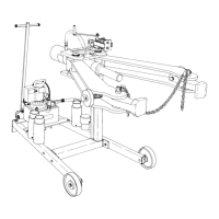
EXTENSION ADAPTERS: See Figure 13
Extension adapters serve as spacers between the ram and the shaft of the object to be
pulled.
Note: Use a pushing adapter (#303045 or #44745) on the end of the ram or on the
end of any combination of extension adapters. When using extension adapters, there
may be sagging away from the centerline as adapters are fitted together.
To correct the alignment, use the following procedure:
1. Before applying hydraulic pressure to an object, lift the pushing adapter to position it
on the common centerline of the object being pulled and the puller head.
2. Lightly apply hydraulic pressure to hold the pushing adapter in position. Check the
alignment. All adapters must be in a straight line and at a 90° angle to the object
being pulled.
3. When not in use, store extension adapters on the puller cart as shown in Figure 11.
SAFETY CHAIN: See Figure 14
1. Use the safety chain (#207516) at all times with this puller.
The puller arms must be hooked and checked before hydraulic
pressure is applied to the object being pulled.
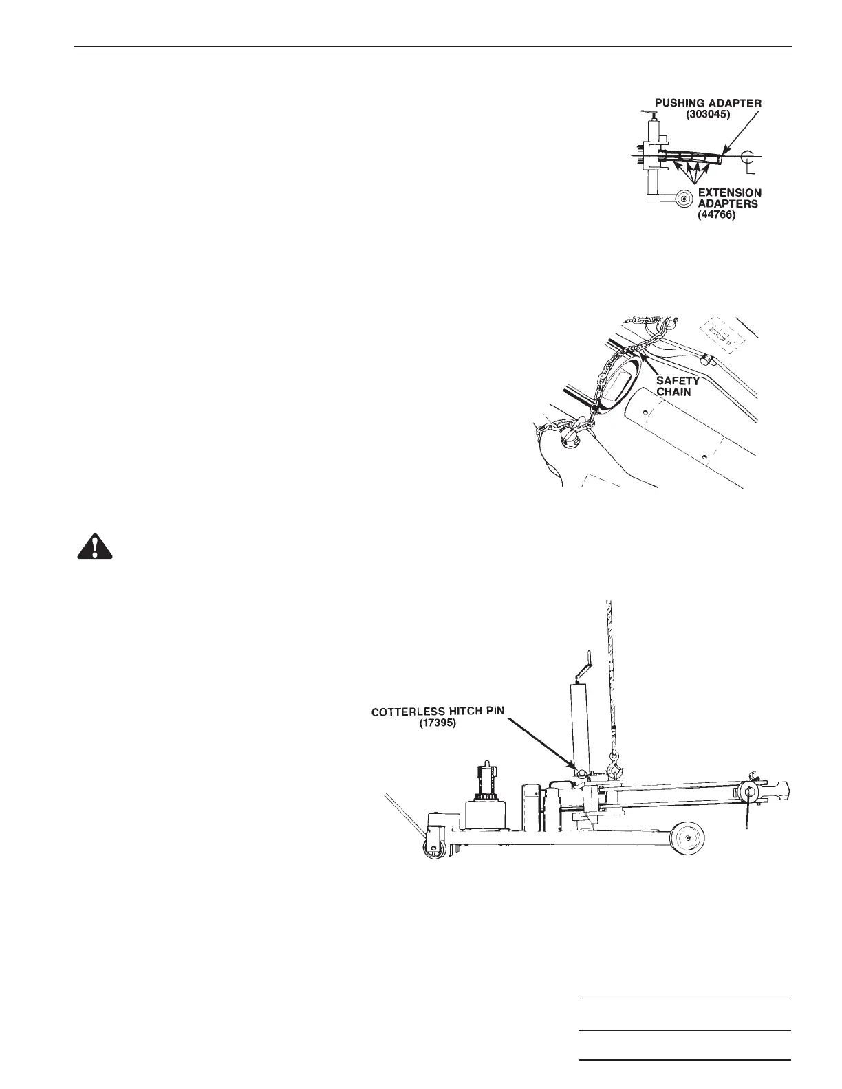
LIFTING INSTRUCTIONS: See Figure 15
WARNING:
To help prevent personal injury, the following steps must be performed if it is necessary to
lift the entire 100 ton puller assembly. The cotterless hitch pin prevents the entire puller head and jaws
assembly from coming off the tube upright.
1. Lower the puller head and jaw assembly
until it is resting on the base.
2. Insert the cotterless hitch pin (#17395)
into the hole located on the tube upright
above the lowered head and jaw
assembly.
3. Hook the crane to the lifting hook located
near the head of the puller jaw assembly.
GENERAL MAINTENANCE
1. Regularly grease the acme screw, wheel zerks, all pivoting pins and the sides of the upright tube.
2. Regularly check the jaw pins for signs of excessive wear.
3. Regularly check the tightness of all nuts and bolts.
4. Look for any obvious signs of damage.
FIGURE 13
FIGURE 14
FIGURE 15
 Loading...