12
UK
11.5.2 Adjustment of operating position without FG flanges
If FG flanges are not available, the ball can, in exceptional cases,
be adjusted as follows.
(Attention! Failure of adjustement is possible.):
Install the ball seals as described in 11.3. Assemble the valve
as described in 11.4. Turn the ball into its exact open position.
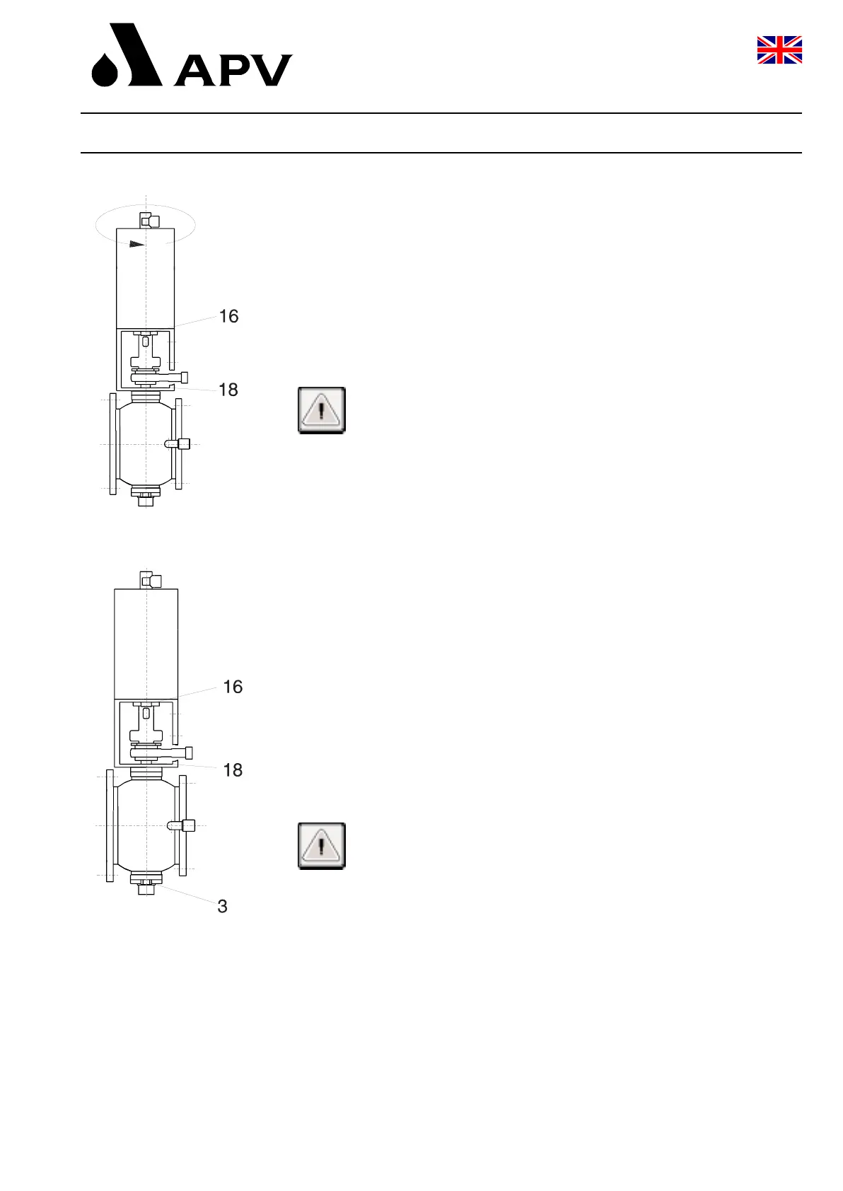
a. Control actuator (15) with pneumatic air (min. 6 bar) and place
it on the yoke (17).
b. Screw in screws item 16, but do not tigthen them.
Danger! Do not reach into the open valve after installation
of the actuator. Risk of injury by sudden operation
of the valve.
! The ball must be in its exact open position !
c. Slightly turn the actuator in anticlockwise direction to adjust the
play in the connecting parts.
!!! The ball must not move during this procedure !!!
(exact open position)
At first, tighten the screws item 18 and then item 16. Operate the
turning actuator several times to check the operating accuracy
of the ball.
d. Shut off the air supply to the turning actuator and insert the valve
in closed position into the line system. Fasten it with the screws.
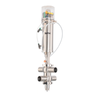
e. Centering of ball (absolutely necessary)
To center the ball between the seal rings, proceed as follows:
1. Release screws item 3 by about ¼ turn.
2. Release one screw item 18 by about ¼ turn.
3. Release second screw item 18 by about ¼ turn and retighten
it immediately.
Attention! Hold the turning actuator fast during this process.
Bring up holding moment in clockwise direction
(top view of actuator).
4. Tighten screw 18 and, then, screw 3.
f. Tightening torque: Md = 16 Nm M8
Md = 40 Nm M10
g. Connect pneumatic air line with turning actuator.
h. Connect cleaning line.
i. Attach valve position indicators.
11. Service Instructions
Double - Seat Ball Valve DELTA DKRT 2
Tank Outlet Valve
Operating Manual : Rev. 4