Q
qparksAug 7, 2025
What to do if valve position movement is missing with actuated solenoid valve SPXFLOW Control Unit?
- BBrenda FloresAug 7, 2025
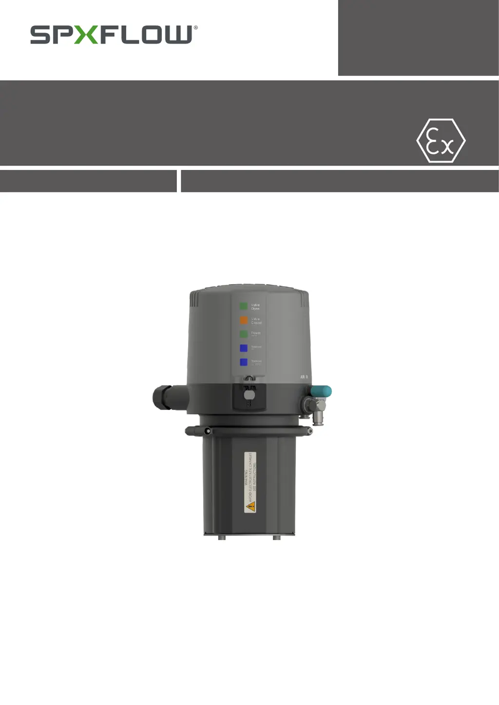
If the valve position movement is missing when the solenoid valve is actuated, verify the correct control unit is installed by checking the label in the type window of the control unit: CU41-D4-AS-interface. Also, check the valve movement with the lever at the solenoid valve, the cabling between the electronic module and solenoid valve, the compressed air supply (minimum 5 bar), and the control air connection between the CU41 and the valve actuator.