Herpstat EZ Series
User’s Manual
www.spyderrobotics.com
Thank you for choosing the Herpstat digital proportional thermostat. This product
offers the following features:
Proportional heating constantly monitors and adjusts amount of heat necessary to maintain a target
temperature (usable range from 70˚F to 110˚F).
Dimming and Pulse heating modes.
Basking Assist control built in to work with basking lights.
Glowing LED snake eyes indicate measured temperature and heat status.
Soft startup slowly applies power during initial warm-ups.
Auto Power Matching constantly adjusts the power output curve to match the enclosures efficiency.
Precision temperature sensors with an internal resolution of .1125 ˚F and are accurate to ± .9 ˚F
Removable sensors allow for easy replacement if necessary.
User replaceable fuse.
Audible alarm system.
30 minute low temperature alarm.
Over temperature alarm.
Internal error detection shuts off heat if sensor fails or is disconnected.
400 total watt output for the Herpstat EZ1
600 total watt output for the Herpstat EZ2
1 year limited warranty.
About this User's Manual
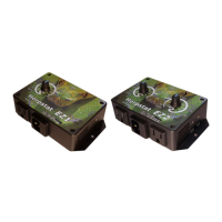
This manual covers both the Herpstat EZ1 and Herpstat EZ2 products. The Herpstat EZ2 adds a second output
and probe with its own independent setting knob.
Hardware Installation
WARNING – FIRE OR ELECTRICAL SHOCK MAY RESULT FROM MISUSE. FOR INDOOR USE ONLY!
Herpstat 1: Do not exceed 400 watts.
Herpstat 2: Do not exceed 300 watts on either output.
1. Each AC receptacle on the Herpstat has a corresponding probe jack on the side of the unit. On the
Herpstat EZ2 the probe jack on the top is used with the left dial and outlet. The lower probe jack
belongs to the dial and outlet on the right side of the unit. On the Herpstat EZ2 its very important to
keep the probe and outlets matched or else an overheat condition can occur.
2. Attach the Herpstat electrical cable to the bottom of the unit and to a standard wall outlet.
3. Attach the heating device to the AC outlet receptacles on the Herpstat. These devices may include
heat tape, heat coils, basking lights, ceramic heat emitters, heat mats or other resistive load heating
devices. Not recommended for use with rock heating devices or other devices that come in direct
contact with the animal. Do not connect oil-filled heaters or other space heaters.
Installation Tips:
We do not recommend using aluminum tape to secure the probes. This can cause false readings and
poor regulation.
Route the probe wires so that they are not in direct contact with the 120vac cables going to the heating devices.
Preferably leave at least a few inches between the probe wires and the AC lines to avoid cross talk/electrical
interference issues.
Mount the device in a dry indoor location away from additional heat and humidity sources. During operation it is
normal for the Herpstat's enclosure to be warm to the touch.
Electrical surges can damage a thermostat. Use a good quality surge suppressor connected between the wall
and Herpstat.
Setup Procedure
Install the probe where you want to measure / regulate temperature. Recommendations on probe placement
can be found on our website here:
http://www.spyderrobotics.com/probe
Adjust the knob to your desired temperature. The indicated temperatures on the thermostat are an
approximate setting in Fahrenheit. Use a separate thermometer in the enclosure and adjust the knob
accordingly to reach your desired temperature. When the knob is adjusted a short double beep will sound and
the LED will flash green indicating that it is recognizing a new temperature. Once it recognizes the dial has
stopped moving a three beep indicator will sound and the LED will flash green acknowledging the change.
NOTE: Any time a knob is adjusted the thermostat will wipe its previously learned power curves and
go through the process of relearning exactly how much power the enclosure needs to maintain the
new temperature. Give the unit time to adjust before determining if further changes are needed.
Checking Device Firmware:
When unit is first plugged in the LED’s will blink the firmware version. The number of red blinks on the left eye
is the whole number and the number of green blinks on the right eye will indicate the tenth of the revision.
Then an audible beep will sound indicating the unit is starting normal operation.