© 2013–2017 Schneider Electric All Rights Reserved
80043-808-02 Rev. 02 I-Line™ Combo Switchboards
03/2017 Appendix 1: Specifications—Typical Wiring
23
ENGLISH
Appendix 1: Specifications
Typical Wiring
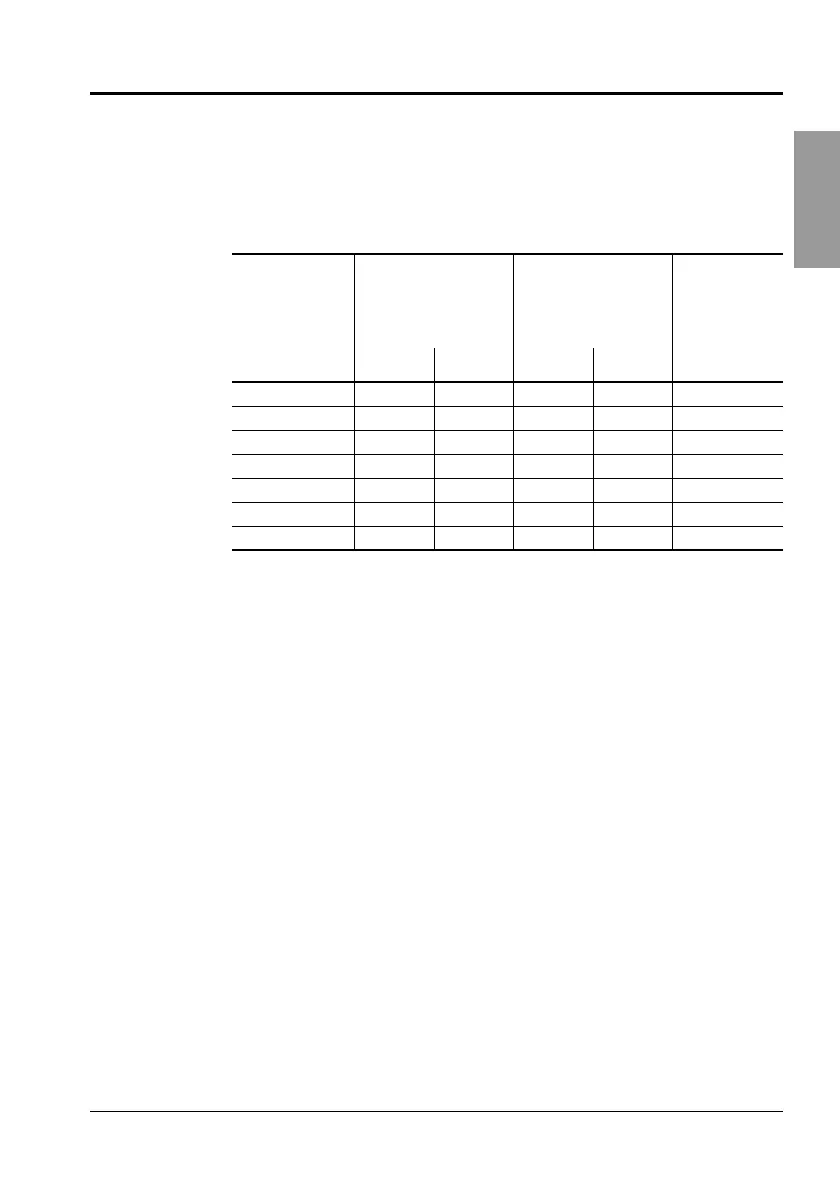
NOTE: Branch connections phasing is determined by the circuit breaker
selected. See the latest catalog or the Digest for circuit breaker selection.
NOTE: Assure that the circuit breaker voltage rating is appropriate for the
system. With the selection of proper units, any of the listed voltage
systems can be used.
I-Line Combo Switchboard Ratings
Refer to NEC section 110-22, 2011 Edition and CEC rule 12-014, 2002
Edition for more information. The series rated system label is located in
the bag assembly. Short circuit tests are conducted at
100–105% of the maximum switchboard voltage.
Table 2: I-Line Combo Switchboards Typical Wiring
1
1-Phase
I-Line Combo
Switchboards
(NQ only)
3-Phase
I-Line Combo
Switchboards
Application
Voltage AC
2
Phase Wires Phase Wires
120/240 Vac 1 3 — — —
208Y/120 Vac — — 3 4 NF/NQ
240 Vac
3
1233NF/NQ
240/120 Vac
3
,
5
— — 3 4 Delta NF/NQ
480Y/277 Vac — — 3 4 NF Only
600Y/347 Vac
4
— — 3 4 NF Only
48 Vdc — — — 2 NQ Only
1
Additional information is provided on the I-Line Combo switchboard. See the main
circuit breaker rating, if used.
2
Unless otherwise specified.
3
For grounded “B” phase system, only circuit breakers rated 240 Vac minimum should
be used. Do not use circuit breakers rated 120 Vac or 120/240 Vac.
4
For use in Canada only.
5
When wiring for delta systems, phases “A” and “C” must be 120 Vac to neutral, with
phase “B” 208 Vac to neutral. Connect only circuit breakers rated 240 Vac minimum,
not 120 Vac or 120/240 Vac to “B” phase.
80043-808-01.book Page 23 Wednesday, March 22, 2017 12:31 PM
 Loading...