71
Technical Manual Gear Hub Systems 2010 · GEN.0000000002002 · Rev. A
SRAM
®
S7
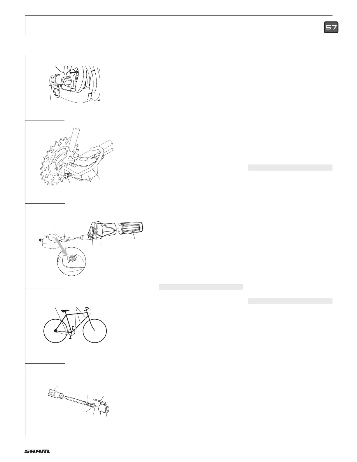
ASSEMBLY
• Turn dust cap (7, Fig. 3) until the three
lugs (8) are between the three beads (9)
on the sprocket (10).
• Position dust cap and push towards
sprocket until it is felt to lock into place.
• Placing the wheel in the rear frame.
• Fit new retaining washer (3,5 mm thick)
on left axle end (1, Fig. 4).
The serrations must bear against the
dropout and the lug must engage in the
dropout slot.
• Fit the hoop guard (1, Fig. 5) on the right
axle side (drive side).
No additional washers or any acces-
sories are permitted.
Advice:
If a different protective bracket is used
the thickness of the attachment plate
must be max. 3 mm.
At least the beginning of the axle
thread must be visible in front of the
axle nut.
• Mount the axle nuts. Tightening torque
on axle nuts 30 – 40 Nm (266 – 350 in.lbs.)
• Version with coaster brake:
Mount the brake lever using a suitable
frame clamp (2, Fig. 4).
Caution:
Mount the brake lever between the two
straps of the frame clamp.
The clamp must be seated on the frame
without play.
Use a self-locking nut! Tightening
torque: 2 – 3 Nm (18 – 27 in.lbs.).
Caution:
Check that all the brake system
components are functioning properly!
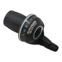
ASSEMBLY SHIFTER
Advice:
• When choosing cable housing lengths,
be sure to allow enough housing for an
extreme turn of the handlebars in both
directions.
• Note also, that different stem lengths
and handlebar positions effects cable
housing length.
• Slide the shifter (1, Fig. 6) onto the
handlebar.
• Slide the handlebar grip (2) onto the
handlebar.
Caution:
Never use lubricants or solvents when
fitting handlebar grips. They have a
safety function and must not come free
from the handlebar.
• Place the shifter on the handlebar grip
and position so that you can use it com-
fortably. Tighten the clamping bolt (3). 3
mm Allen key, torque 3.5 – 4 Nm (31 – 35
in.lbs.).
Caution:
• Check that shifter and brake lever
can be easily operated (if necessary,
realign).
• Never ride without handlebar grips. The
turning grip of the twist shifter could
become loose. This can result in severe
injuries.
• When fitting the cable avoid small radi-
us. Attach the cable 3 times to the down
tube (1, Fig. 7).
• Last attachment point is on the lower
rear wheel fork (2, Fig. 7) immediately
behind the chain wheel.
Cable housing must be movable inside
attachment.
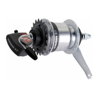
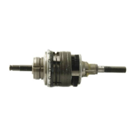
INSTALLING CLICKBOX
• Insert shift rod (1, Fig. 8) in shift tube (2)
(oil parts lightly) and then push into axle
bore as far as the stop. Turn slot (6) in
shift tube to a position where it is easily
visible.
• Push locating sleeve (3) with guiding rib
(4) to the front onto the hub axle – mak-
ing sure that the internal lug (5) is guid-
ed in the slot (6) of the shift tube until it
can be felt – and heard – to engage.
• Turn locating sleeve on the axle until
the guiding rib (4) is facing roughly
upwards.
• Place shifter in gear position “1“.
• Push on Clickbox (2, Fig. 5) to the stop
on the hub axle. The guiding rib (4, Fig.
8) of the locating sleeve thereby engag-
es in the slot on the housing. In the end
position tighten up the knurled bolt (3,
Fig. 5) by hand (0.3 Nm / 2.7 in.lbs.).
ADJUSTMENT
• Be sure to reset rotational shifter from
5th to 4th gear.
• Match up the marks in the Clickbox
viewing window (4, Fig. 6) by turning
the barrel adjuster (5).
Caution:
Check that all the brake system
components are functioning properly!
4
6
7
8
1
3
2
1
4
5
2
3
7
6
4
5
2
1
3
1
2
5
1
2
 Loading...