Control Board Features
READ “FREQUENTLY ASKED QUESTIONS”
ON PAGES 20 – 24 BEFORE OPERATING THE
STOVE.
The Control Board controls all functions of the stove
by monitoring sensors that are in the system. These
sensors serve 2 purposes.
a. General Operation of the Stove.
b. Safety Features, to shut the unit down in the
event the sensors detect a problem in the unit.
The Control Board also has Diagnostic Capabilities to
help in diagnosing 3 areas in the Stove. These areas
are:
1. High Temperature Limit.
2. Proof of Fire Sensor
3. Vacuum in the Firebox
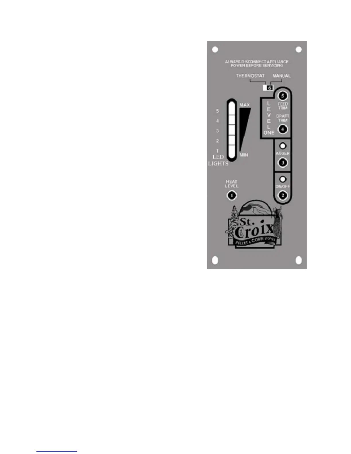
A closer look at the Control Board to the right in
figure 2 will explain how the board works. There are
five buttons labeled 1 through 5, a slide switch labeled
6 and a LED Light bar with 5 Heat Settings. The LED
Light bar is also used during the Diagnostic process,
see page 8 for more details.
The buttons on the board function as follows: (Refer to
Figure 2. The touch pad buttons and Slide Switch are
labeled with the white numbers 1 through 6)
1. The Heat Level button (1) will advance the
setting between level 1 and 5. Once you reach level 5,
it will drop back to level 1. Each level has a LED light
to indicate where the board is set.
2. The On/Off button (2) turns the Stove On and
Off. It will also reset the board after the board has
sensed a problem and is flashing a Diagnostic code.
3. The auger button (3) will allow the customer to
manually auger corn into the burn pot on start up when
needed. This is particularly helpful in priming the
Auger Tube when it is empty.
4. The Draft Trim button (4) allows for adjusting the
Exhaust fan voltage on Heat Level 1 only. Push the
button and the all of the LED Lights in the light bar
will flash once. This decreases the draft fan voltage
Figure 2
approximately 5 volts below the default setting. Push the
button a second time and all of the LED Lights in the light
bar will flash twice. This decreases the voltage
approximately another 5 volts. Pushing the button a 3
rd
time will reset the voltage to the default setting. This
adjustment is available to fine tune the #1 Heat Level
draft setting. This would only be used in the case the
Stove was hooked up to a tall Vertical Chimney (see point
11 on page 23 for more information)
5. The Feed Trim button (5) will allow the Fuel feed
rate to be adjusted on Heat Level 1 only. Heat Level 1
should be seen as the Pilot setting of the Stove, when
operating on a Thermostat. Pushing the Feed Trim button
(5) will switch between the different adjustments. Heat
Level one can be adjusted in the following ways:(see
points 10 & 11 on pages 22 & 23).
6
Lancaster Operations & Maintenance Manual