AN2544 Circuit operation
5/17
1.3 Inductor selection
A starting point for the inductor operating in discontinuous mode can be derived from the
following formula which gives a good approximation of the inductor.
Equation 1
Where Id
peak
is the minimum peak drain current, 320 mA for the VIPer12A-E and 560 mA for
the VIPer22A-E, f is the switching frequency at 60 kHz. The maximum peak current limits
the power delivered in the buck topology. Therefore, the calculation above is for an inductor
that operates in discontinuous mode. If the current swings down to zero, than the peak
current is twice the output. This limits the output current to 280 mA for a VIPer22A-E. If the
inductor is a larger value, operating between continuous and discontinuous mode, we can
reach 200 mA comfortably away from the current limit point. C6 has to be a low ESR
capacitor to give the low ripple voltage
Equation 2
D5 needs to be a fast recovery diode but D6 and D8 can be standard diodes. DZ1 is used to
clamp the voltage to 16 V. The nature of the buck topology is to peak charge at no-load. A
Zener 3 to 4 V higher than the output voltage is recommended.
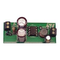
1.4 Design example
Figure 3 is the schematic for the evaluation board. It is set up for 12 V with a maximum
current of 350 mA. If less current is required, then the VIPer22A-E can be changed to a
VIPer12A-E and C2 can be decreased from 10 µf to 4.7 µF. This delivers up to 200 mA.
Figure 4 shows the same board but for 16 V output or higher, D6 and C4 can be left out. The
jumper bridges the output voltage to the V
dd
pin.
1.5 Design hints and trade-off
The value of L determines the boundary condition between continuous and discontinuous
mode for a given output current. In order to operate in discontinuous mode, the inductor
value has to be lower than
Equation 3
Where R is the load resistance, T is the switching period, and D is the duty cycle.
There are two points to consider. One is, the more discontinuous the higher the peak
current. This point should be kept lower than the minimum pulse by pulse current limit of the
VIPer22A-E which is 0.56 A. The other is if we use a larger value inductor to run continuous
all of the time, we run into excess heat from switching losses of the MOSFET inside the
VIPer. Of course, the inductor current rating must be higher than the output current to
prevent the risk of saturating the core.
L2
Pout
Id
peak
()
2
f•
--------------------------------
•=
V
ripple
I
ripple
Cesr•=
L
1
2
---
RT 1D–()•••=