DESIGN DETAILS
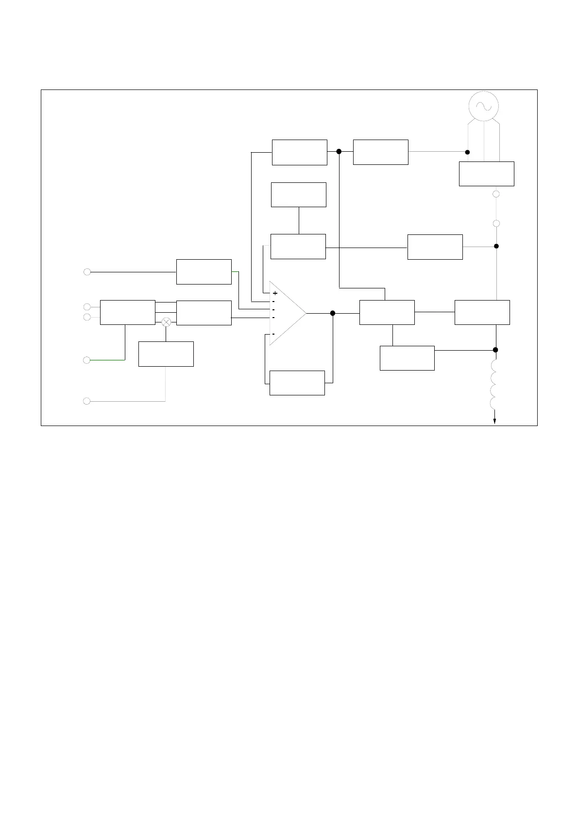
The main functions of the AVR are:
Sensing Resistors take a proportion of the generator output
voltage and attenuate it. This input chain of resistors includes the
range potentiometer and hand trimmer which adjust the generator
voltage. An isolating transformer is included to allow connection
to windings of different polarity and phase. An operational
precision rectifier converts the ac sensing voltage into dc for
further processing.
Quadrature droop circuit converts the current input into a
voltage which is phase mixed with the sensing voltage. The result
is a net increase in the output from the sensing network as the
power factor lags, causing the reduction in excitation needed for
reactive load sharing of paralleled generators.
A trimmer allows control over the amount of droop signal.
Offset Control provides an interface between the AVR and
accessories.
Power Supply components consist of zener diodes, dropper
resistors and smoothing to provide the required voltages for the
integrated circuits.
Precision voltage reference is a highly stable temperature
compensated zener diode for dc comparison.
Soft Start circuit overrides the precision voltage reference
during run-up to provide a linear rising voltage.
Main Comparator/Amplifier compares the sensing voltage to
the reference voltage and amplifies the difference (error) to
provide a controlling signal for the power device.
Stability circuit provides adjustable negative ac feedback to
ensure good steady state and transient performance of the
control system.
Power Control Driver controls the conduction period of the
output device. This is achieved by pedestal and ramp control
followed by a level detector and driver stage.
Power Control devices and rectifier vary the amount of exciter
field current in response to the error signals produced by the main
comparator.
Synchronising circuit provides a short pulse near the zero point
of one of the phases on the PMG and is used to synchronise the
Under Frequency Roll Off (UFRO) and power control circuits to
the generator cycle period.
UFRO circuit measures the period of each electrical cycle and
reduces the reference voltage linearly with speed below a
presettable threshold. A light emitting diode (LED) gives
indication of underspeed.
Engine Relief (load acceptance) circuit causes greater voltage
roll off (makes the volts/Hz slope steeper) to aid engine speed
recovery after application of a "block" load.
Overload detector continuously monitors the level of excitation
and provides signals to shut down the output device if overloads
last more than ten seconds. An overload condition produces a
latched fault requiring the generator to be stopped for reset.
PMG
POWER
RECTIFIER
SYNC
CIRCUIT
UFRO
ENGINE
RELIEF
SOFT
START
CIRCUIT
EXCITATION
CIRCUIT
BREAKER
(OPTIONAL)
POWER
SUPPLIES
PRECISION
VOLTAGE
REFERENCE
AMPLIFIER
POWER
CONTROL
DRIVER
POWER
CONTROL
DEVICES
OVERLOAD
DETECTOR
+ INHIBIT
STABILITY
CIRCUIT
EXCITER
STATOR
OFFSET
CONTROL
ACCESSORY
INPUT
GENERATOR
VOLTAGE
SENSING
REMOTE
VOLTAGE
TRIMMER
CURRENT
INPUT
SENSING
RESISTORS
DROOP
ISOLATION +
AVERAGE
CONVERTER
 Loading...