FITTING AND OPERATING
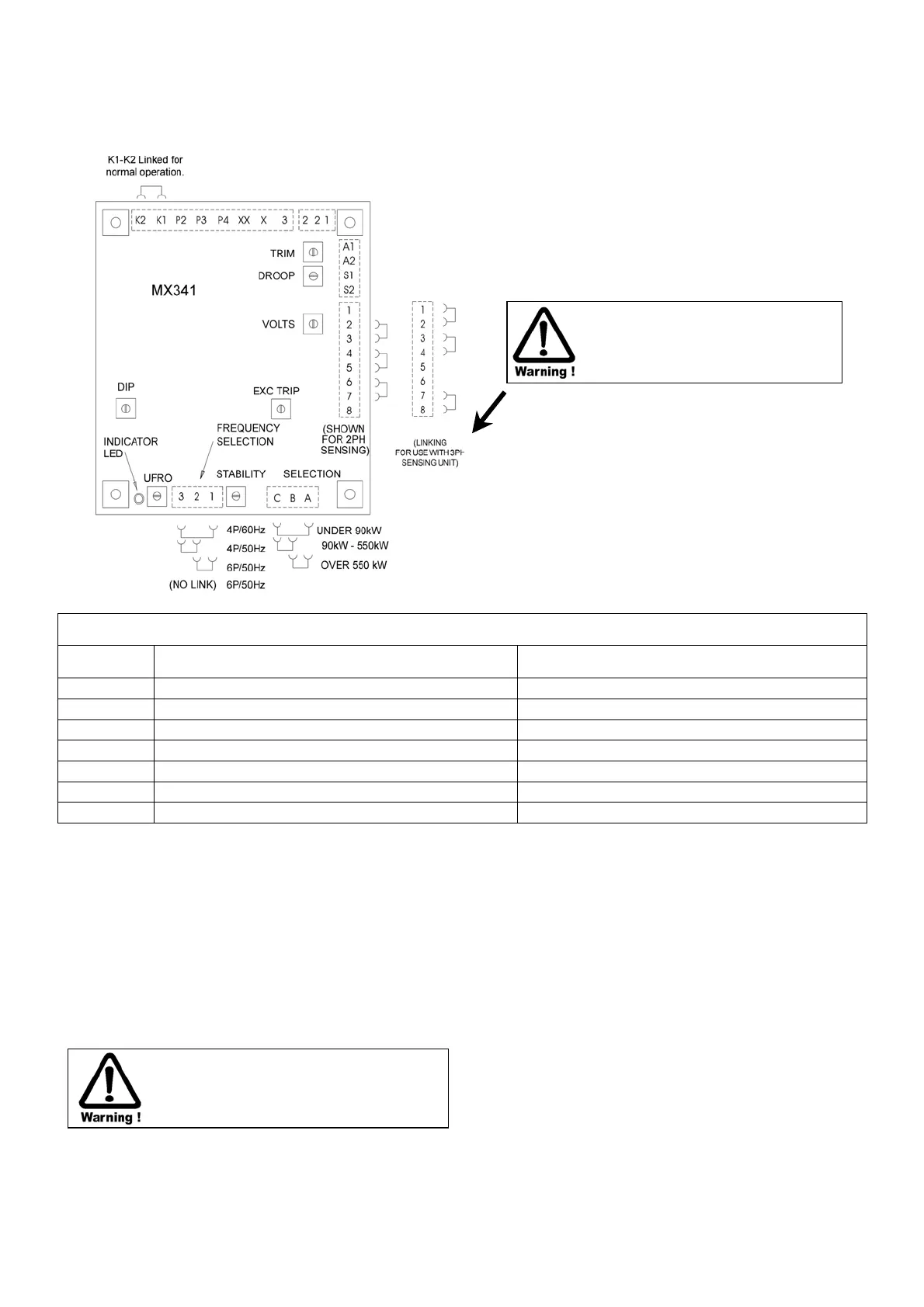
SUMMARY OF AVR CONTROLS
CONTROL FUNCTION DIRECTION
VOLTS
TO ADJUST GENERATOR OUTPUT VOLTAGE CLOCKWISE INCREASES OUTPUT VOLTAGE
STABILITY
TO PREVENT VOLTAGE HUNTING CLOCKWISE INCREASES STABILITY OR DAMPING EFFECT
UFRO
TO SET UNDER FREQUENCY ROLL OFF KNEE POINT CLOCKWISE REDUCES THE KNEEPOINT FREQUENCY
DROOP
TO SET GENERATOR OR DROOP TO 5% AT FULL LOAD 0 PF CLOCKWISE INCREASES THE DROOP
V/TRIM
TO MATCH AVR INPUT TO ACCESSORY OUTPUT CW. ALLOWS THE ACCESSORY MORE CONTROL OVER AVR
EXC TRIP
TO SET THE OVEREXCITATION CUT OFF LEVEL CLOCKWISE INCREASES THE CUT OFF LEVEL
DIP
TO SET THE INITIAL FREQUENCY RELATED VOLTAGE DIP CLOCKWISE INCREASES THE VOLTAGE DIP
The AVR is fully encapsulated to ensure long trouble-free
operation. It is usually fitted on a panel of the terminal box. It
can also be separately fitted in a switchboard.
ADJUSTMENT OF AVR CONTROLS
VOLTAGE ADJUSTMENT
The generator output voltage is set at the factory, but can be
altered by careful adjustment of the volts control on the AVR
board, or by the external hand trimmer if fitted. Terminals 1 &
2 on the auxiliary terminal block in the generator terminal box
will be fitted with a shorting link if no hand trimmer is required.
Do not increase the voltage above the
rated generator voltage. If in doubt, refer
to the rating plate mounted on the
generator case.
If a replacement AVR has been fitted or re-setting of the
VOLTS adjustment is required, proceed as follows:-
1) Before running generator, turn VOLTS control fully anti-
clockwise.
2) Turn remote volts trimmer (if fitted) to midway position.
3) Turn STABILITY control to midway position.
4) Connect a suitable voltmeter (0-300V ac) across line to
neutral of the generator.
5) Start generator set, and run on no load at nominal
frequency e.g. 50-53Hz or 60-63Hz.
6) If the red Light Emitting Diode (LED) is illuminated, refer
to the Under Frequency Roll Off (UFRO) adjustment.
7) Carefully turn VOLTS control clockwise until rated voltage
is reached.
8) If instability is present at rated voltage, refer to stability
adjustment, then re-adjust voltage if necessary.
9) Voltage adjustment is now completed.
A separate 3 Phase Sensing unit is
needed. Do not connect as shown
unless a 3 Phase Sensing unit is
fitted. (See sheet 5515)
 Loading...