ASSEMBLY INSTRUCTIONS
9
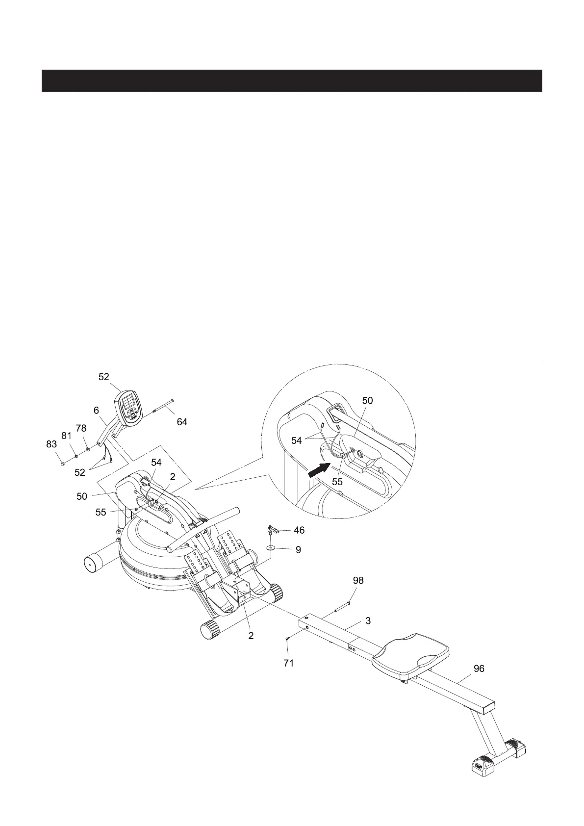
STEP 3
Attach the SHORT RAIL(3) to the MAIN FRAME(2) with BUTTON HEAD BOLT(M6x1x15mm)(71) and
BARREL NUT(M8x1.25x88mm)(98). Lock the RAIL(3) in unfold position with the FIXING LEVER(46) and
LARGER WASHER(ø10.5mmxø40mmx3mm thick)(9).
NOTE: After tightening the FIXING LEVER(46) the rear stabilizer of the BASE FRAME(1) might be raised
o the oor slightly, this is normal, it will rest on the oor once you are seated.
STEP 4
Install two AA batteries into the METER(52), the batteries are not included. See page 13 for detailed
battery installation instructions. Attach the METER POST(6) to the MAIN FRAME(2) with BUTTON HEAD
BOLT(M8x1.25x130mm)(64), WASHER(M8)(78), LOCK WASHER(M8)(81), and ACORN NUT(M8x1.25)
(83).
STEP 5
Refer to the detail view. Clip the GROMMET(55) onto both SENSOR WIRES(54), then press the
GROMMET(55) into the LEFT COVER(50). Connect the SENSOR WIRES(54) to the CONNECTION WIRES
of the METER(52). Push the excess wires back into the LEFT COVER(50).