6
length
length
mm.
in.
INCHES
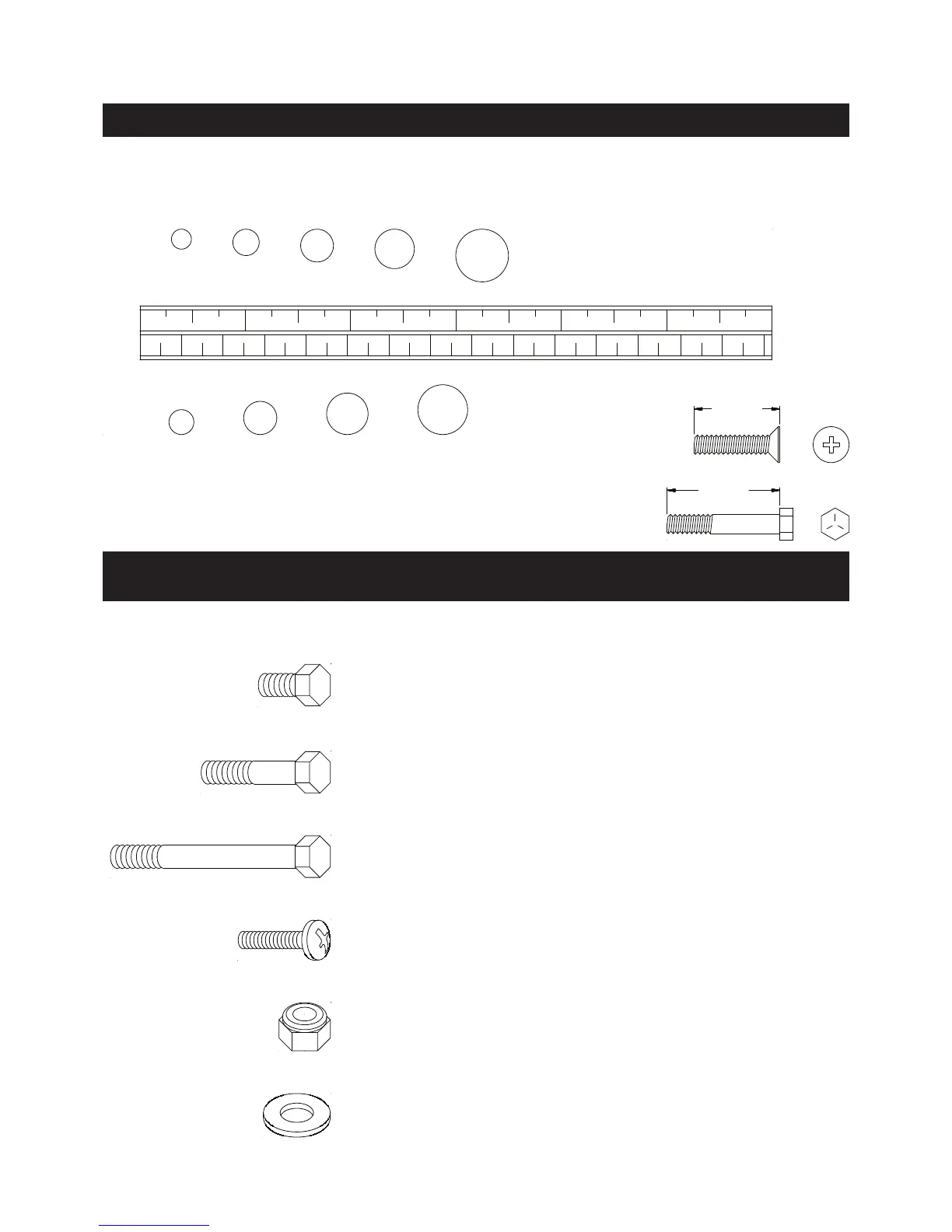
This chart is provided to help identify the hardware used in the assembly process. Place the washers or
the ends of the bolts or screws on the circles to check for the correct diameter. Use the small scale to
check the length of the bolts and screws.
NOTICE: The length of all bolts and screws, except those with flat
heads, is measured from below the head to the end of the bolt
or screw. Flat head bolts and screws are measured from the
top of the head to the end of the bolt or screw.
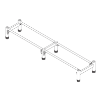
After unpacking the unit, open the hardware bag and make sure that you have all the following items.
Some hardware may be already attached to the part.
MILLIMETERS
0 10 20 30 40 50 60 70 80 90 100 110 120 130 140 150
0 1/2 1 1/2 2 1/2 3 1/2 4 1/2 5 1/2 6
6 8 10 12
3/16" 1/4" 5/16" 3/8" 1/2"
HARDWARE IDENTIFICATION CHART
Part No. and Description Qty
20 Bolt, Hex Head (M10 x 1.5 x 20mm) 4
17 Bolt, Hex Head (M10 x 1.5 x 65mm) 2
19 Bolt, Hex Head (M10 x 1.5 x 75mm) 1
18 Bolt, Hex Head (M10 x 1.5 x 120mm) 1
21 Bolt, Hex Head (M10 x 1.5 x 140mm) 2
22 Bolt, Round Head (M6 x 1 x 34mm) 4
23 Nylock Nut (M10 x 1.5) 6
24 Washer (M10) 18