44 45
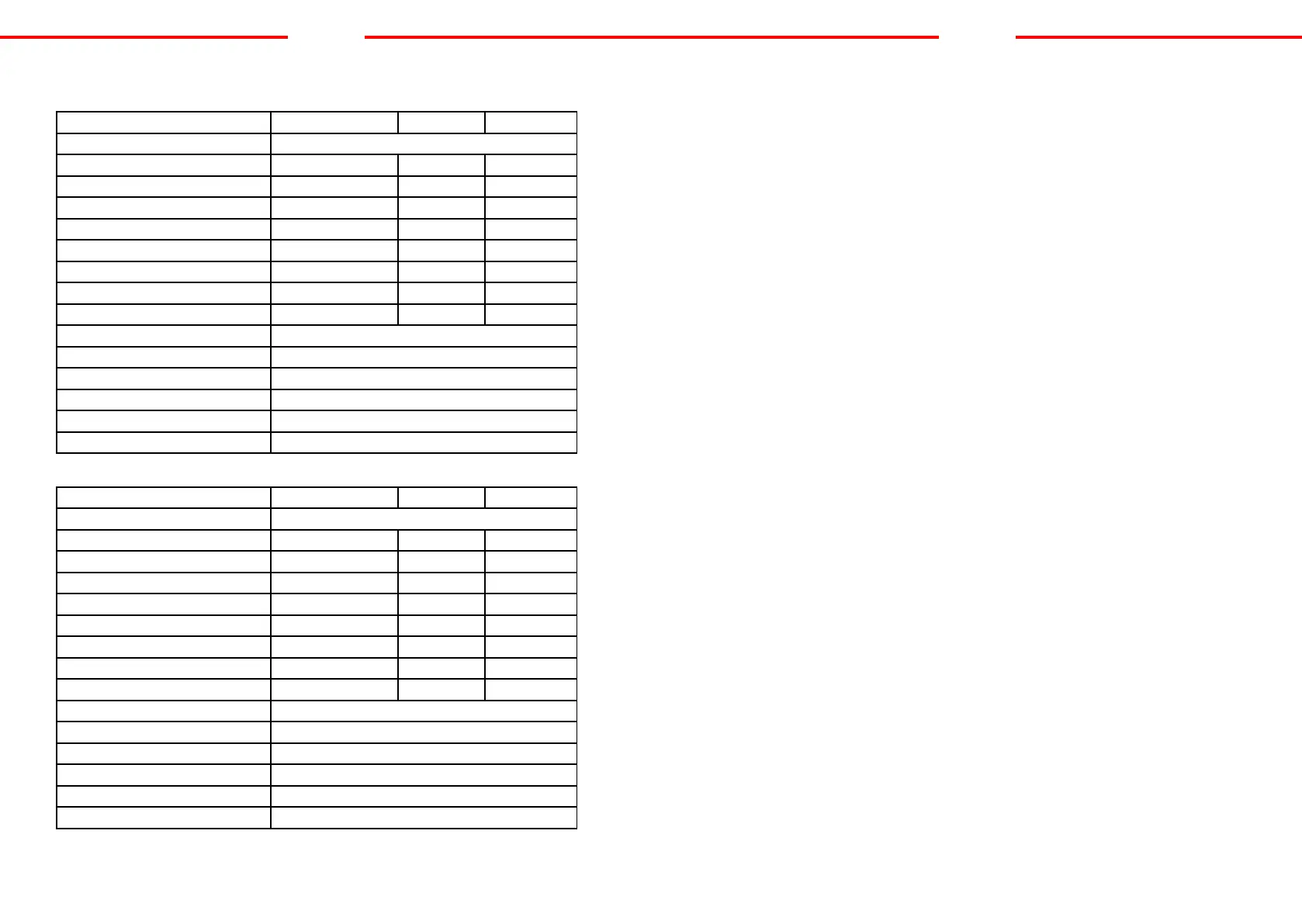
Technical details
S-Multi 51 / 51P WIG MMA CUT
Network frequency (Hz) 50/60
Ignition HF: high frequency Contact Contact
Open circuit voltage (V) 62 62 250
Input current (A) 23,5 28 29
Welding current (A) 10 - 180 10 - 165 10 - 50
Compressor connection (Bar) - - 4,5
Gas ow (L/min.) 2 - 5 - 80 - 200
Electrode diameter max 1-3,2mm 1 - 4mm 1,2mm
Cutting capacity at max. 50 A - - 1 - 16mm
Model input voltage 230V, 1-Phase
Power factor (COSf) 0.93
Performance (%) 85
Weight (KG) 15
Dimensions (mm) 425x205x355
Protection class IP21
S-Multi 41 / 41P WIG MMA CUT
Network frequency (Hz) 50/60
Ignition HF: high frequency Contact Contact
Open circuit voltage (V) 52 52 230
Input current (A) 18 22 25
Welding current (A) 10 - 160 10 - 160 10 - 40
Compressor connection (Bar) - - 4,5
Gas ow (L/min.) 2 - 5 - 80 - 200
Electrode diameter max. 1-3,2mm 1 - 4mm 1,2mm
Cutting capacity at max. 40 A - - 1 - 12mm
Model input voltage 230V, 1-Phase
Power factor (COSf) 0.93
Performance (%) 85
Weight (KG) 13
Dimensions (mm) 425x205x355
Protection class IP21
EN
INITIATING OPERATION
A. Unpacking
Unpack all the items out of the box and make sure that you have received all items
listed on the packing list.
B. Work environment
Make sure that the work area is well ventilated. The unit is cooled by an axial fan that
provides an air ow for the electronics through the rear panel.
(Note! The panel must be installed in a way where the vent holes are located closer to
the front of the device.)
Leave at least approx.15 cm at the front and 15 cm on each side for cleaning.
If the machine is operated without adequate cooling, the length of the duty cycle will
be reduced greatly.
C. Cable connections
Each unit is equipped with a main power cable, which is responsible for providing cur-
rent and voltage to the device. If the device is connected to power which exceeds the
required voltage, or if the wrong phase is set, it may lead to severe damage to the unit.
This is not covered by the warranty for the equipment and the user will be responsible
for such situations.
D. Torch connection
Connect the torch to the inverter by connecting the air tube that is attached at the
end of the torch to the torch connector on the front part of the machine. Ensure that
the connection is secure by tightening it slightly with a spanner. However you should
not make it too tight.
EN