6
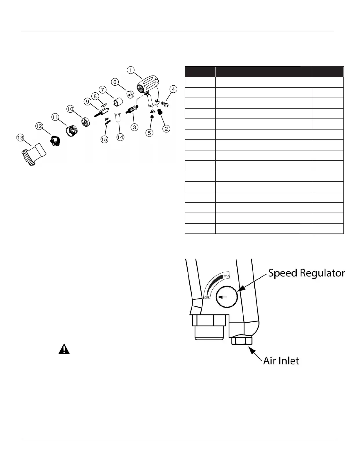
SP-A2 Series Spare Parts List
Ref. Number Description Part Number
1 Housing Assembly
317-A-A40
2 Inlet Bushing
317A-3B
3 Trigger Assembly
317A-A93
4 Regulator Assembly
317-A249
5 Muffler Kit
317A-AMK1
6 Rear End Plate Assembly
317A-A12
7 Cylinder
317-A3
8 Vanes (4 required)
317A-42-4
9 Rotor
317A-53
10 Front End Plate Assembly
317A-A11
11 Motor Lock Nut
317A-27
12 Motor Coupling
8333
13 Adaptor
3170
14 Trigger Plate (SP-A2P Only)
3176
15 Trigger Plate Screws (3 Required) (SP-A2P Only)
3177
Description: The SP-A2P air motor is equipped with
a plate which permanently locks the trigger in the "ON"
position. The speed of the motor can be adjusted by
turning the speed regulator on the side of the motor handle
between the "OFF" position and the "MAX" position.
Operation: Prior to connecting an air source to the
air inlet of the SP-A2P, ensure that the speed regulator dial
is in the "OFF" position (See Figure 1). Once the air source
has been connected and the discharge hose of the pump
tube is in it's desired location, the speed regulator dial can
be turned toward "MAX". Upon completion of the pumping
process, the speed regulator dial should be returned to the
"OFF" position. Failure to do so can result in severe
injury.
Figure 1
Standard Pump Operating Instructions and Parts Manual (OIPM-IND-1019)


 To Next Page
 Loading...