Do you have a question about the Standard C58 and is the answer not in the manual?
Lists important warnings and precautions to follow before operating the unit.
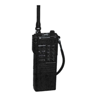
Connector for the supplied helical antenna for portable operation.
Combines power switch, volume control, and noise blanker on/off function.
Suppresses FM background noise when no signal is present.
Digital VFO control knob for tuning frequencies.
Key to store selected channel frequencies in memory.
Key switch to select desired frequency band (144-147 MHz).
Key to recall stored channel frequencies from memory.
Selects channel frequency stepping interval (5/25 kHz, 1 kHz, 100 Hz).
Scans up through selected MHz band frequencies.
Transmits a tone burst signal for repeater driving.
Scans channel frequencies stored in memory.
Initializes unit operation mode.
Accepts the supplied microphone.
LCD readout for frequency and mode display.
Checks signal strength, power, and battery voltage.
Indicates when the unit is in transmission mode.
Selects operation mode (USB, LSB, FM, CW).
Selects simplex, R1, or R2 repeater modes.
Adjusts receiver tuning frequency without changing transmission frequency.
Controls display lamps and battery check function.
Resets the internal microprocessor to its initial state.
Screw for opening the battery compartment.
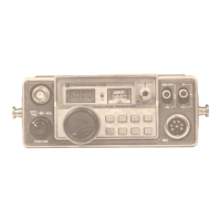
Lists features on the side panel.
Selects channel frequency scan stepping (5/25 kHz).
Button to transmit.
Buttons for channel frequency stepping.
Instructions for installing battery packs.
Precautions for handling dry cells to prevent leakage or bursting.
How to handle microprocessor malfunctions.
Microprocessor back-up when using external power.
How to use the mode switch for different operations.
Instructions for tuning and using the digital VFO.
Explains frequency indications for S, R1, and R2 repeater modes.
Function of the CALL key for tone burst transmission.
Transmitting tone burst using the PTT button.
Step-by-step guide to store frequencies into memory.
Recalls stored frequencies sequentially from memory.
Scans all frequencies in the selected MHz band.
Scans frequencies stored in memory addresses M1-M5.
Indicates received signal strength.
Indicates transmitter's emission power.
Indicates supply voltage when in BAT CHECK mode.
Details the internal workings of the receiver section.
Details the FM transmitter's signal path and modulation.
Explains the SSB transmitter's signal path and modulation.
Explains how the tone burst generator works.
Details the functional blocks within the PLL integrated circuit.
Details the microprocessor's functions and inputs/outputs.
Lists control outputs from the microprocessor.
Input for initial clearing of the microprocessor.
Inputs from matrix circuits.
Key for selecting MHz bands.
Key for selecting channel step intervals.
Key to cancel features.
Key for scanning memory frequencies.
Key for scanning all frequencies.
Key to recall stored frequency data.
Key to store data into memory.
Switch for selecting operation mode.
Explains VFO selection modes (Simplex, Repeater).
Control for the noise blanker.
Control for scan operation.
Control for switching stepping intervals.
Feature to reduce microprocessor power dissipation.
Control section behavior in TX mode.
Explains the back-up power circuit.
Steps to remove the unit's case.
Steps to remove the front bracket.
Procedure to remove the PLL control board.
Standard conditions required for alignment.
List of instruments needed for alignment.
List of tools needed for alignment.
Adjusting shift voltage in different modes.
Adjusting comparative oscillation.
Adjusting programmable counter input.
Procedure for VCO alignment.
Adjusting output parameters.
Aligning 100 Hz stepping for Band A.
Aligning 100 Hz stepping for Band B.
Adjusting output frequency.
Procedure for aligning the RIT control.
Aligning subcarrier frequency in different modes.
Adjustment related to the younger amplifier stage.
Adjusting linear amplifiers for optimal power.
Aligning FM deviation and SSB transmission power.
Aligning SSB carrier suppression.
Aligning RF output power and battery check meter.
Adjusting SSB receiver sensitivity.
Adjusting FM receiver sensitivity.
Aligning the noise blanker circuit.
Adjusting the S meter for reception and output.
Covers frequency, emission type, stability, power, and dimensions.
Details reception system, IF, sensitivity, and selectivity.
Covers power output, modulation, and deviation.
| Brand | Standard |
|---|---|
| Model | C58 |
| Category | Transceiver |
| Language | English |