Do you have a question about the Stanford Research Systems SR620 and is the answer not in the manual?
Details on selecting the correct AC line voltage for the instrument.
Information on selecting the correct line fuse for operation.
Guidance on using the detachable three-wire power cord.
Specifies range, trigger rate, resolution, error, and arming modes for time interval measurements.
Details range, error, gate options, and display resolution for frequency measurements.
Defines standard and optional timebase specifications like frequency, aging, and stability.
Guides on setting the measurement mode, source, and arming mode.
Explains how to select and view statistical information on the LED display.
Details on setting trigger levels, slopes, input termination, and UHF prescalers.
Describes arming modes for time interval measurements like +TIME and ±TIME.
Explains frequency measurement modes, gating options, and accuracy.
Details on inserting adjustable delays between EXT input trigger and arming.
Configuration for GPIB, RS-232 baud rates, and data transfer.
Settings for instrument calibration and timebase source selection.
Defines scope displays, hardcopy device, DVM scales, and jitter representation.
Overview of remote programming via RS232 and GPIB interfaces.
Explains the structure of commands, mnemonics, arguments, and terminators.
Details commands for controlling measurements like *TRG, ARMM, and AUTM.
Lists and explains error indicators like STOP LED, START LED, and CLOCK LED.
Common software and hardware issues encountered with RS-232 communication.
Tests verifying front panel, internal self-tests, and trigger input functionality.
Tests confirming the sensitivity of A, B inputs, and UHF prescalers.
Verifies the accuracy of the rear panel DVM inputs.
A basic calibration procedure that usually suffices for most cases.
Procedure for calibrating insertion delay for various inputs and slopes.
Steps to calibrate the DVM inputs for accuracy.
Detailed description of the SR620's Z8800 processor and memory architecture.
Explanation of different ways start and stop circuits can be armed.
Description of the circuitry used to measure time intervals with high resolution.
List of components and their references for the front panel assembly.
Comprehensive list of components on the main circuit board.
| Channels | 2 |
|---|---|
| Operating Temperature Range | 0°C to 50°C |
| Input Impedance | 1 MΩ or 50 Ω |
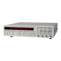
| Display | 16 character alphanumeric |
| Dimensions | 8.5" W x 3.5" H x 13" D |
| Jitter | 25 ps RMS |
| Input Voltage Range | ±5 V |
| Interfaces | RS-232 |
| Input Sensitivity | 10 mV |