16
77-117
17
77-117
P
1
D
2
1
2
P
1
D
1
D
1
2
D
1
2
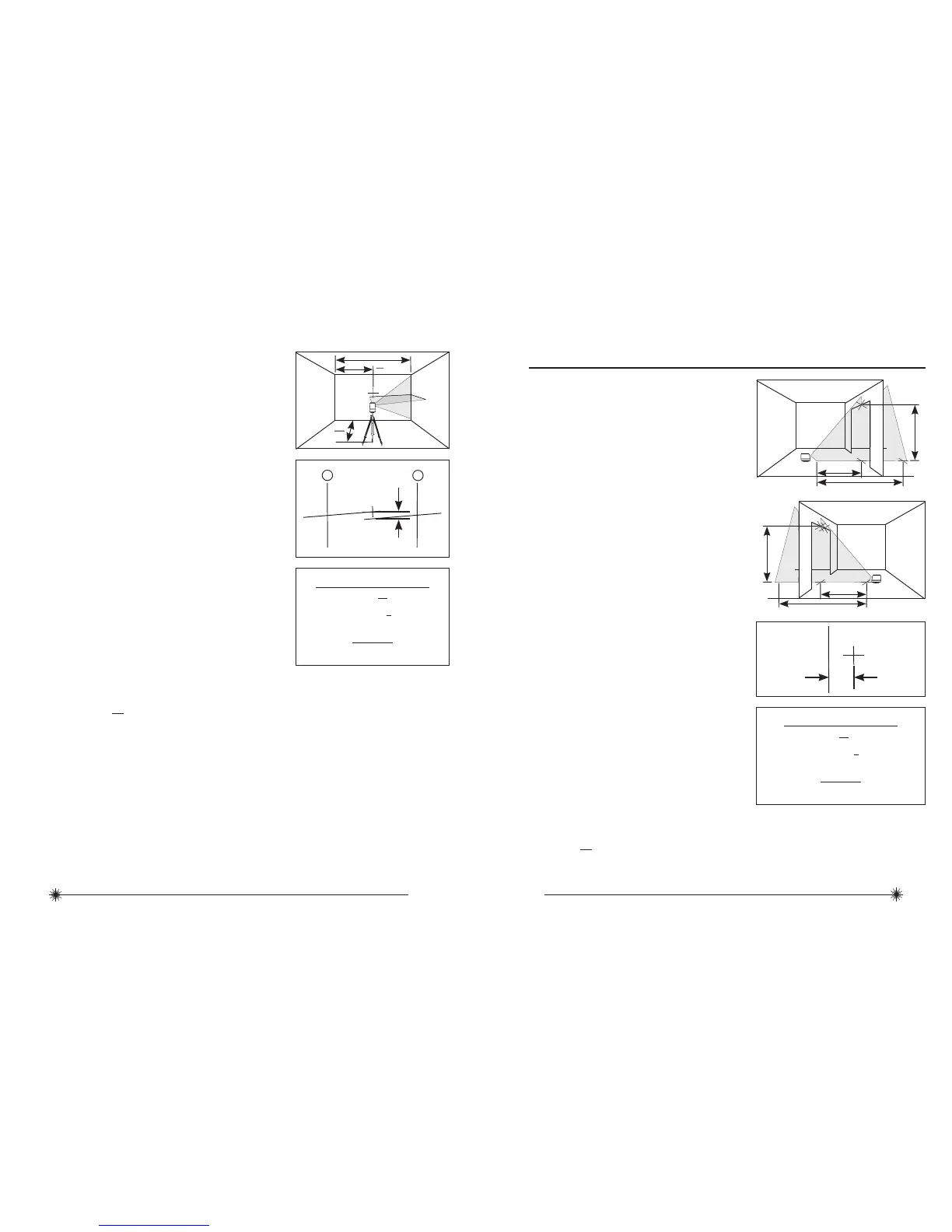
2. Rotate laser unit to other corner or
reference point.
3. Measure the vertical distances between
P
1
and the horizontal beam from the 2nd
location.
4. Calculate the maximum allowed offset
distance and compare to D
2
. If D
2
is
not less than or equal to the calculated
maximum offset distance the unit must be
returned to your Stanley Distributor.
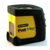
Vertical Beam Accuracy
P
1
D
1
P
2
P
3
D
1
2 x D
1
P
4
D
1
P
2
P
3
D
1
2 x D
1
P
1
P
1
D
2
1. Measure the height of a door jamb or
reference point to get distance D
1
. Place
laser unit as shown with laser ON. Aim
vertical beam towards door jamb or
reference point. Mark points P
1
,
P
2
, and
P
3
as shown.
2. Move laser unit to opposite side of door
jamb or reference point and align vertical
beam with P
1
and P
2
.
3. Measure the horizontal distances between
P
1
and the vertical beam from the 2nd
location.
4. Calculate the maximum allowed offset
distance and compare to D
2
. If D
2
is
not less than or equal to the calculated
maximum offset distance the unit must be
returned to your Stanley Distributor.
Example: D
1
= 5 m, D
2
= 1 mm
0,5 x 5 m = 2,5 mm (maximum allowed offset distance)
1 mm ≤ 2,5 mm (TRUE, unit is within calibration)
mm
m
Compare:
D
2
≤
Max
Maximum Offset Distance:
Max
in
ft
= 0,006 x D
1
ft
mm
m
= 0,5 x D
1
m
Example: D
1
= 2 m, D
2
= 1 mm
1 x 2 m = 2 mm (maximum allowed offset distance)
1 mm ≤ 2 mm (TRUE, unit is within calibration)
mm
m
Compare:
D
2
≤
Max
Maximum Offset Distance:
Max
in
ft
= 0,012 x D
1
ft
mm
m
= 1 x D
1
m