GB
14
Performing Accuracy Check
and Calibration
NOTE:
• The laser tool is sealed and calibrated at the factory to the
accuracies specied.
• It is recommended to perform a calibration check before use.
• Be sure to allow the laser tool adequate time to Auto-Level (<
30 seconds) prior to a calibration check.
• The laser tool should be checked regularly to ensure its
accuracies, especially for precise layouts.
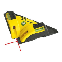
Horizontal Check
See Figure Ⓞ
1.
Set the laser tool on a tripod 20 m away from a wall with the
"+X" side facing the wall (Figure Ⓞ①).
2.
Power ON the laser tool. Allow the laser tool to Auto-Level
and be sure the laser is rotating.
3.
Mark a reference point "D
1
" where the laser line appears on
the wall. If available, use a detector to more easily locate
the beam.
4.
Loosen the laser tool from the tripod and rotate the laser
tool 180°. The "-X" side should now be facing the wall
(Figure Ⓞ②). Mark a reference point "D
2
" where the laser
line appears on the wall.
5.
Measure the vertical distance between reference points "D
1
"
and "D
2
" (Figure Ⓞ③).
6.
If the distance "D
1
" to "D
2
" is < 2.0 mm, calibration is not
required.
RL 600 & RL 600L
If the distance "D
1
" to "D
2
" is ≥ 3 mm, then calibration
is necessary.
RL 700L & RL 750L-G
If the distance "D
1
" to "D
2
" is ≥ 2 mm, then calibration
is necessary.
7.
Rotate the laser 90°. Repeat steps
1.
through
6.
for
the Y-axis. Replace "+X" with "+Y" and "-X" with "-Y"
(Figure Ⓞ④).
Horizontal Calibration
See Figure Ⓞ
1.
Rotate the laser to the same position as step
1.
of the
Horizontal Check procedure (with the "+X" side facing the
wall).
2.
With laser tool powered OFF, press and hold the key
followed by the key.
3.
Release the key and continue to hold the key for ≥ 3
seconds.
4.
Release the key.
5.
The LED ashes GREEN when the laser tool is in
X-axis Calibration mode.
6.
If necessary, adjust the X-axis by using the key and the
key to align the beam with D
0.
D
0
is the halfway point
between the points D
1
and
D
2
established during the X-axis
check (Figure Ⓞ③).
NOTE: Pressing the key or the key slopes the axis
by 0.01° (4.4 mm @ 25 m). Figure Ⓜ illustrates how the
arrow keys affect each axis.
7.
Press the key again to set the X-axis and proceed to the
Y-axis adjustment. The LED ashes RED when the
laser tool is in Y-axis Calibration mode.
8.
Rotate the laser to the same position as step
7.
of the
Horizontal Check procedure (with the "+Y" side facing the
wall).
9.
If necessary, adjust the Y-axis by using the key and the
key to align the beam with D
0.
D
0
is the halfway point
between the points D
1
and
D
2
established during the Y-axis
check.
10.
Press the key again to set the Y-axis and exit Calibration
Mode.
Axis settings are now saved. Calibration Mode is OFF and
the laser tool begins Auto-Levelling.
11.
Repeat the Horizontal Check procedure to determine if the
calibration was successful.
If the laser tool can still not be calibrated after following
the Calibration procedure, send the laser tool into an
Authorized Service Center for repair.

 Loading...