12 ► IW16 User Manual
OPERATION
2. Connect hoses from the hydraulic power source to the tool ttings or quick disconnects. It is good practice to
connect the return hose rst and disconnect it last to minimize or eliminate trapped pressure within the wrench.
3. Observe the ow indicators stamped on the main body assembly and the hose couplers to ensure that the ow
is in the proper directions. The female couple on the tools “IN” port is the inlet (pressure) coupler.
Note: If the uncoupled hoses are left in the sun, pressure increase within the hoses can make them dicult
to connect. Whenever possible, connect the free ends of hoses together.
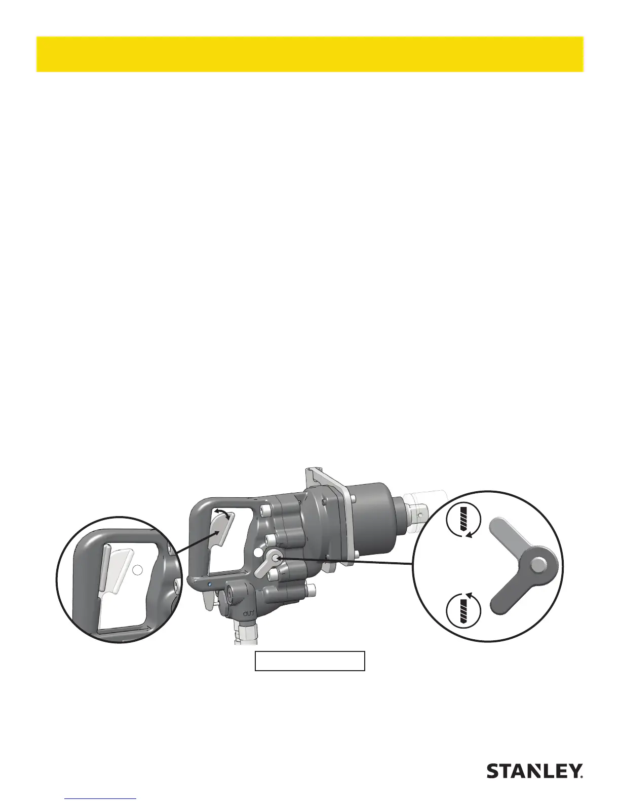
WRENCH OPERATION - FIG. 3
The IW16 is designed for 1-inch square hex drive. The 1-inch drive conguration is used with drive sockets for high
impact (500–2500 ft lb / 680–3400 Nm) installation and removal of fasteners.
During normal operation it is common to see some grease leakage from around the anvil during hard use. Refer to
the IW16 Service Manual for the correct lubrication procedures.
Use at the low end of the 500–2500 ft lb / 680–3400 Nm torque range during continuous use over long periods of
time (impact times exceeding 10 seconds). The high temperature generated in the impact mechanism can reduce
steel part and lubricant durability within the wrench.
1. Observe all Safety Precautions.
2. Move the hydraulic circuit control valve to the “ON” position to operate the wrench.
3. Select the direction of impact desired using the reversing valve located on the side of the wrench. To select
clockwise direction, place the valve in the upward position. To select counter-clockwise direction, place the
valve in the downward position.
Note: To more accurately tighten bolts, lubricate threads, check with a torque wrench and duplicate time of
impacting for other bolts of the same length and thread size.
4. Squeeze the trigger to activate the wrench.
Note: Hold the tool correctly and be ready to counteract normal or sudden movements. Have both hands
available.
5. Release the trigger to stop the wrench.
6.
Figure 3 - Tool Use
3
4

 Loading...