GENERAL DESCRIPTION
MIG welders which can weld flux cored gasless wire. When welding,
use promig jet welding spray to obtain optimal welding. the use of
this product will enhance the binding of the weld and reduce
spattering.
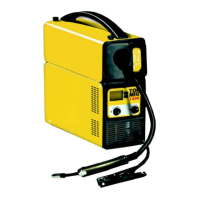
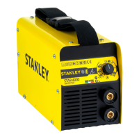
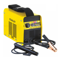
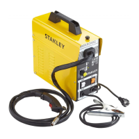
DESCRIPTION OF THE MACHINE
1. ON/OFF switch
2. Min-Max Switch
3. Wire speed regulator
4. Fuse LED
5. Power LED
6. Thermal protection LED
ELECTRICAL CONNECTION
Before connecting the machine to the outlet, check that your supply
voltage is like the machine’s voltage and that the furnished power is
sufficient to feed the full load machine. Make sure that the electric
plant is provided with a sufficient earth connection.
EARTH CONNECTION
A suitable earth cable connected to a clamp is supplied with the
welding machine. The earth clamp should be attached to the
workpiece itself. It must be a very good connection wherever made,
as a poor or dirty connection will produce difficult welding conditions
and could result in a bad weld.
TECHNICAL INFORMATION
The welding machine has an On-Off switch (1), with luminous led
that indicates the operation of the car (5). The welder has a switch
(2) that provides 2-position power, to select based on the power of
which need is had. Using the knob (3) placed on the frontal you can
regulate the welding wire speed. The knob should be used in
conjunction with the voltage switch to give a smooth and perfect arc.
The machine is fitted with a thermal overload protection which will
automatically interrupt the welding current on reaching excessive
temperatures; in which instance a yellow pilot light (6) will switch on.
Once the temperature has decreased to a level low enough to allow
welding, the light will switch itself off and the machine is ready for use
again. The wire speed control electronic card is protected against
peak voltage by means of an easy fuse located on the wire setting
card (4).
SPOOLS INSTALLATION
You can use spools of Ø 100mm (0.1 Kg, 0,5 Kg).
WIRE-FEEDER MOTOR
Make sure that the size of the groove in the feed roll corresponds to
the welding wire size being used. The machines are arranged with
feed roll Ø 0.9mm. The feed roll has the wire diameter stamped on its
side. The machines are equipped with proper shagreneed rolls
suitable for welding with flux cored wire without gas protection. In any
case, the machine uses only wire type FLUX.
FEEDING WIRE INTO THE WELDING TORCH
Cut the first 10 cm of wire and then check that there are no burrs or
distortions at the cut end. Release the small wheel which is
connected to the pressure arm by unscrewing the pressure screw
and pass the wire through the feed roll’s groove and then re-insert
the wire into the guide. At this point, make sure that the wire lies in
the feed roll’s groove in a natural line. Drop the pressure arm on the
wire and swing it back under the pressure screw. Pressure on the
welding wire is regulated by turning the pressure screw, the correct
pressure being critically important to the smooth operation of the
welding machine. The optimum pressure is the one which ensures
that the wire runs smoothly though allows the feed roll to slip in the
event of a blockage in the torch. It is possible to adjust the friction of
the paddle hub. If the hub over-runs, then increase the friction
pressure in order to always have the spool wire drawn. On the
contrary, if the friction pressure is too much, some tension can be
released to obtain a regular wire feeding.
TORCH CONNECTION
The torch is connected directly to the welding machine so it is ready
for use. A probable replacement of the torch must be done with care
and if possible by a technician. To replace contact tips, it is
necessary to unscrew or to pull it. Replace tip, check that it
corresponds with the wire size and replace the gas shroud. For good
wire feeding during welding operations, it is essential that the correct
size parts are used for each wire. Always Keep clean the contact tip.
WELDING GUIDE
When welding on the lowest output settings, it is necessary to keep
the arc as short as possible. This should be achieved by holding
welding torch as close as possible and at an angle of approximately
45 degrees to the workpiece.
The arc length can be increased when welding on the highest
settings, an arc length up to 20 mm can be enough when welding on
maximum settings.
GENERAL WELDING TIPS
From time to time, some faults may be observed in the weld owing to
external influences rather than due to welding machine’s faults. Here
are some that you may come across :
- Porosity
Small holes in the weld, caused by break-down in gas coverage of
the weld or sometimes by foreign bodies inclusion. Remedy is,
usually, to grind out the weld. Remember, clean well the working
place and finally incline the torch while welding.
· Spatter
 Loading...