G
B
20
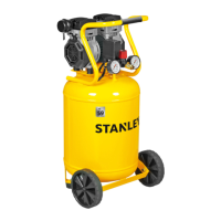
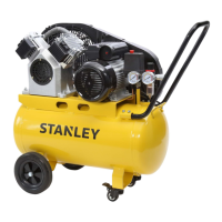
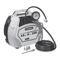
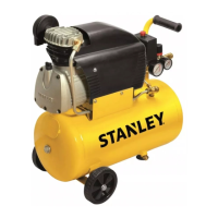
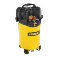
2. LAYOUT (Fig. 1 - 11)
1. Intake air lter
2. Pressure vessel
3. Wheel
4. Supporting rubber foot
5. Quick-lock coupling (regulated compressed air)
6. Pressure gauge (for reading the preset pressure by
means of the pressure regulator)
7. Pressure regulator
8. I/O switch (ON/OFF)
9. Transportation handle
10. Safety valve
11. Drain valve
12. Pressure gauge (for reading the tank pressure)
13. Quick-lock coupling (unregulated compressed air)
14. Screw
15. Nut
16. Washer
3. PACKAGING CONTENTS LIST
● Air compressor
● Air lter
● Suction tube
● Instruction manual and other documents
4. SCOPE OF USE
The compressor is designed for generating compressed
air for tools operated by compressed air.
Please note that our equipment has not been designed for use
in commercial, trade or industrial applications. Our warranty
will be voided if the machine is used in commercial, trade or
industrial businesses or for equivalent purposes.
The machine is to be used only for its prescribed purpose.
Any other use is deemed to be a case of misuse. The user/
operator and not the manufacturer will be liable for any
damage or injuries of any kind caused as a result of this.
5. POINTS TO NOTE WHEN SETTING
UP THE COMPRESSOR
● Examine the machine for signs of transit damage. Report
any damage immediately to the company which delivered
the compressor.
● The compressor should be set up near the working
consumer.
● Avoid long air lines and long supply lines (extensions).
● Make sure the intake air is dry and dust-free.
● Do not set up the compressor in damp or wet rooms.
● The compressor may only be used in suitable rooms (with
good ventilation and an ambient temperature from +5°C to
+40°C). There must be no dust, acids, vapors, explosive
gases or inammable gases in the room.
● The compressor is designed to be used in dry rooms. It
is prohibited to use the compressor in areas where work
is conducted with sprayed water.
6. ASSEMBLY AND STARTING
Warning!
You must fully assemble the appliance before using it
for the rst time.
6.1 Fitting the wheel kit
If provided, the wheel kit must be installed as shown in
gure 2.
6.2 Fitting the supporting feet
If provided, the rubber feet must be tted as shown in
gure 3.
6.3 Fitting the transport handle (for
models envisaging this)
Screw the transport handle to the compressor as shown
in gure 4.
6.4 Fitting the air lter
Remove the transportation stop with a screwdriver or
similar and screw the air lter (ref. 1) securely to the
equipment (Fig. 5a-5b).
If supplied, insert the suction tube inside the lter cover
(Fig. 5c).
6.5 Assembling the quick coupler (if not
already assembled)
Tighten the quick coupler for regulated pressure to the
coupling on the outlet as shown in gures 6a and 6b.
6.6 Fitting the quick-lock coupling for
tank pressure (for models envisaging
this)
Screw the quick-lock coupling for unregulated tank
pressure (ref. 13) to the pressure vessel (ref. 2) as shown
in Figures 7a and 7b.
6.7 Voltage
The compressor is equipped with a mains cable with
shock-proof plug. Insert the plug of the electric cable
in a socket of suitable shape, voltage and frequency
complying with current regulations. Before you use the
machine, make sure that the mains voltage complies with
the specications on the rating plate. Make sure that the
ON/OFF switch is not in the I (ON) position. Long supply
cables, extensions, cable reels etc. cause a drop in
voltage and can impede motor start-up. In the case of low
temperatures below +5°C, motor start-up is jeopardized as
a result of stiffness.
6.7.1 Connection of the mains plug (electrical
information for the BS plug)
Important!
The wires in the mains lead tted to this product are
coloured in accordance with the code shown in g. 12.
● The 3 pin plug must comply to BS1363/A.
● Fuse must comply to BS1362.
 Loading...