Page 6
PROCEDURE
1. Unpack all parts and inspect for
damage.
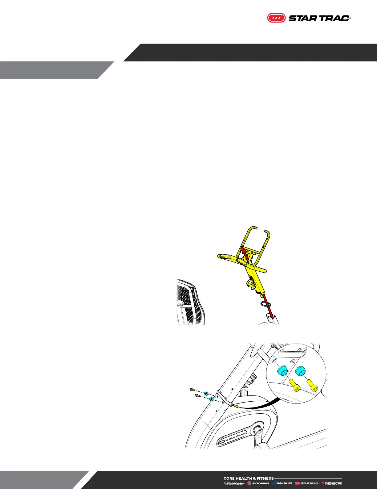
2. Route the wires through the mast
beauty ring (740-9313-XX), then up and
out of the top of the mast.
3. Once the wires are routed, insert the
mast (720-5272-XX) into the base
frame.
Fig. 6
4. Use a 6mm allen key to finish securing
the mast to the base frame using four
(4) pieces each of the M8 counter-bore
washer (718-5693) and M8 x 20mm
socket head cap screw (730-0889).
Fig. 7
Assembly instructions cover either 10” touchscreen or LCD console. For 15” Embedded, please see the
console manual 620-8816 for additional wiring and configuration information.
Required Tools:
• Metric Socket Set
• Metric Allen Key Set
• Torque Wrench
• #2 Phillips Screwdriver
• 3/4” Open-ended Wrench
• 9/16” Open-ended Wrench
IF INSTALLING PVS - PLEASE REFER TO PVS INSTALL INSTRUCTIONS FOR ROUTING THE COAX
CABLE BEFORE CONTINUING WITH UNIT BASE ASSEMBLY.
ASSEMBLY