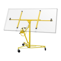
4
ASSEMBLY
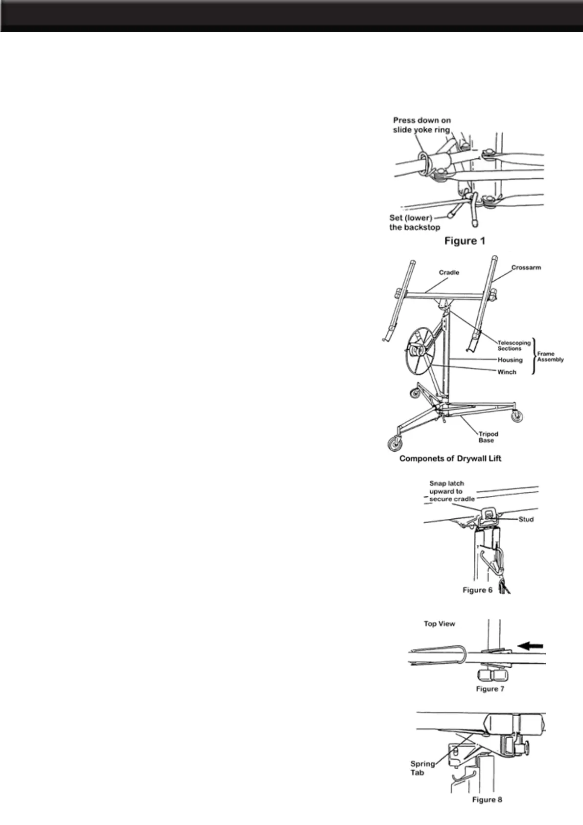
COMPONENTS:
The Drywall Lift is shipped as several components that must be assembled before use:
• Tripod base assembly.
• Frame assembly, which includes a winch assembly and standard (4-ft) telescoping lift sections
• Cradle assembly, without its detachable crossarms
• Two cradle crossarm assembly
ASSEMBLY PROCEDURE:
1. Set up the tripod base:
A. Set the base on the oor, resting on its casters.
B.
Press down on the slide yoke ring. Hold the ring down while
you swing the two forward legs out until the yoke ring snaps into
the locking hole on the bottom of the slide tube. (See Figure 1)
C. To prevent the tripod base from rolling backward during
assembly, lower the backstop as shown.
2. Set the frame assembly onto the two “V” angles on the tripod
base, and lower the frame about 1 in. until it is secured by the
angles. Before continuing, be sure the frame is pushed all the way
down and is held securely by the angles.
3. Attach the handle to the winch wheel. Tighten the nut, then back
it off slightly so the handle turns freely.
4. Move the winch assembly into its working position:
A. Hold the winch wheel and brake arm as shown in Figure 2.
Rotate the winch wheel forward slightly while you lift on the brake
arm to release the brake.
B. Raise the brake arm all the way up. Grasp the winch post, and
grip the brake arm rmly with your thumb. (Figure 3)
C. Place your right hand on top of the frame. Continue to grip
the brake arm as needed to prevent cable backlash, and pull the
winch assembly all the way toward you. (Figure 4)
D. When the winch is fully extended (away from the frame housing),
release the brake arm and swing the retaining hook away so it no
longer secures the telescoping sections inside the frame housing.
5. Press the winch assembly slightly back toward the frame. This
automatically engages the slide bar lock to keep the winch fully
extended. (Figure 5)
IMPORTANT: Before continuing, be sure that the slide bar lock
is fully engaged that is, rotated clockwise as far as possible.
 Loading...