Do you have a question about the Starrett 2900 Series and is the answer not in the manual?
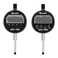
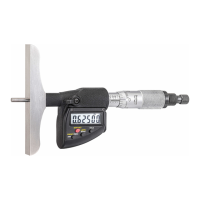
Identifies the top part of the indicator stem.
Describes the flexible protective cover for the spindle.
The sensing tip that touches the workpiece.
The movable measuring rod of the indicator.
Cover for the data communication port.
The main body holding the indicator mechanism.
Compartment for the indicator's batteries.
Mounting feature on the rear of the indicator.
Warning against dropping the precision instrument.
Protect from heat, cold, and direct sunlight.
Prevent impacts and sideways force on the spindle.
Shield from impacts when mounted by stem.
Avoid over-tightening mounting clamps.
Keep spindle clean and lubricate sparingly.
Do not alter the indicator unless specified.
Avoid damaging buttons during operation.
Employ correct stands or holders for intended jobs.
Advised to read related sections first.
Instructions for battery installation.
Prepare the sensing tip for measurement.
Mount the indicator on a suitable device.
How to turn the device on.
Choose between inch or millimeter display.
Orient the indicator perpendicular to the surface.
Procedure to set the zero point.
Steps for taking a measurement.
How to turn the device off.
Steps the indicator follows after battery replacement.
Visual feedback during the startup process.
How to start the zeroing process.
Understanding the display feedback during zeroing.
Specifies battery requirements and usage.
Details the power-saving sleep mode.
Codes indicating the indicator's operating mode.
Structure of the serial data output.
Baud rate, data bits, parity, stop bits.
Timing for data transfer.
Details the function of each pin on the connector.
Voltage thresholds for logic states.
Defines low and high voltage levels for output.
Specifies temperature, humidity, and atmosphere limits.
Describes protection against dust ingress.
Details resistance to water submersion.
Items required to maintain IP67 rating.
Controls power on/off.
Sets reading polarity.
Resets the display to zero.
Toggles between inch and metric units.
Enables advanced functions like Preset and Limits.
Activates Go/No Go limit checking.
Activates the preset value function.
Zeroes display or enables Absolute mode.
Displays min/max values and total indicator runout.
Prepares the indicator for setting a preset value.
Procedure to input the desired preset number.
Steps to access the preset setting function.
Navigates through digits for setting values.
How to input negative preset numbers.
Steps to leave the preset mode.
Initial steps to activate the limits function.
Enters the mode for setting upper/lower limits.
Procedure to capture the lower acceptable value.
Procedure to capture the upper acceptable value.
Activates the limit comparison display.
Accesses the minimum limit setting.
Records the minimum limit.
Accesses the maximum limit setting.
Records the maximum limit.
How to leave the limit setting function.
Initial setup for capturing min/max values.
Steps to record the lowest measurement.
Steps to record the highest measurement.
Locating the minimum reading on the workpiece.
Locating the maximum reading on the workpiece.
Shows the total indicator runout.
Instructions for repeating the min/max/TIR process.
Indicates where the data port is located.
How to remove the data port cover.
Steps to attach the data cable.
How to remove the battery compartment.
Guide for inserting new batteries.
Mentions the default back mounting.
Notes that contact points can be swapped.
Refers to further details on special contact points.
Lists available back mounting accessories.
Lists specialized contact points.
Details available contact point extension lengths.
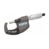
| Brand | Starrett |
|---|---|
| Model | 2900 Series |
| Category | Measuring Instruments |
| Language | English |