Do you have a question about the Starrett MVR300 and is the answer not in the manual?
Identifies key physical parts of the MVR metrology units, including stage and optics.
Describes user interfaces and power input locations on the metrology unit.
Provides general, electrical, and mechanical safety guidelines for operating the system.
Details on connecting the AC adapters for the metrology unit and PC.
Describes post-installation functional checks, calibration, and operator training.
Approach for using telecentric lenses for high accuracy Field-of-View (FOV) measurements.
Strategy for using zoom optics for measuring large parts or high magnification needs.
Routine checks to ensure system safety, cleanliness, and basic functionality.
Procedures to verify zoom optics parfocality, parcentricity, and squareness.
Verifying image focus consistency across magnification changes.
Ensuring features remain centered in the image at different magnifications.
Process for periodically confirming system accuracy using a verification standard.
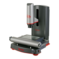
The Starrett MVR200 and MVR300 are manual video metrology systems designed for precise dimensional measurements. These advanced benchtop systems are built on a granite base for stability, ensuring accurate and repeatable results. They utilize recirculating ball linear guides for smooth stage motion and feature a motorized Z-axis for vertical positioning. All electronics, except for the system's PC, are housed within the Z-column, contributing to a clean and integrated design with minimal external wiring.
The primary function of the MVR Series is to perform high-accuracy dimensional measurements on various parts. This is achieved through a combination of high-resolution video imaging, precision optics, and sophisticated metrology software. The systems are capable of 3-axis measurements (X, Y, and Z) and 2D geometrical constructs, including points, lines, angles, and rectangles.
The MVR systems employ 0.5 micron resolution linear encoders to provide superb metrology performance. A high-resolution color video camera captures live images of the part, which are displayed on a 21.5-inch all-in-one touch screen PC. The image can be resized using zoom, and measurements can be taken by simply tapping features on the screen.
Two-channel LED lighting is integrated into the system: an LED ring light for surface illumination and collimated LED sub-stage lighting for profile measurements. This versatile illumination allows for optimal viewing of different part characteristics and features.
The systems run MetLogix M3 FOV software under Windows® 7 Professional. This software not only supports measurement functions but also allows for the import of DXF CAD files (with the M3 DXF/FOV option pack). This enables automatic comparison of actual measurements to CAD data, streamlining inspection processes.
The MVR Series offers flexibility in optics, catering to different measurement needs. Basic MVR200 and MVR300 systems come with factory-installed 6.5:1 manual zoom optics. For enhanced versatility, MVR200 FOV and MVR300 FOV systems feature a bayonet lens mount, allowing users to quickly change optics between the 6.5:1 manual zoom lens and a selection of six fixed magnification telecentric lenses (0.30X, 0.50X, 0.80X, 1.0X, 2.0X, 4.0X). This quick-change capability allows users to switch between zoom operation and field-of-view (FOV) measurements with different magnifications.
When using telecentric optics, the strategy is to perform high-accuracy, high-throughput FOV measurements. If all measurements fit within the FOV, the highest magnification lens that encompasses the entire part is selected. For larger parts, the stage can be moved, and the M3 software seamlessly integrates FOV measurements with encoder readings.
With zoom optics, magnification can be continuously adjusted. This is ideal for measuring large parts that wouldn't fit into a single FOV, or for smaller parts requiring extremely high magnification. The parcentricity feature of the zoom optics ensures that a feature remains at the optical center of the video image throughout the magnification range, simplifying measurements at varying zoom levels.
Illumination is a critical aspect of accurate video-based measurement. The M3 software provides slider controls to adjust light levels. Users are advised to start with lower light and gradually increase it while viewing the image on the monitor to avoid washed-out images or blooming. Maintaining constant lighting during a measurement run is crucial for consistent results. Experimenting with the balance of available light sources (surface and sub-stage) can help bring out specific part features.
Magnification strategy involves balancing resolution and the ability to discern edges. Higher magnification generally provides greater resolution and accuracy, but excessively high magnification can exaggerate edge defects. Users are encouraged to decrease magnification until the edge is most clearly identifiable.
Proper part fixturing is essential to prevent movement during measurement. Aligning the part with the system's X, Y, and Z axes improves dimensional measurement accuracy. The M3 software also allows for the creation of reference frames to compensate for orientation or skew errors.
The system's operator controls are intuitively placed. Manual X and Y axis travel is controlled by hand wheels, with an additional knob for X-axis motion on the right side. A three-position toggle switch on the left side provides fine/coarse speed control for Z-axis travel, while a proportional speed control switch on the right side allows for up-down Z-axis travel. An on-off switch is located on the back right of the metrology unit, and another on the all-in-one PC.
The MVR systems are designed for durability, but periodic maintenance is recommended to ensure peak operating condition. Daily inspections include verifying a clean, dry, and debris-free work area, ensuring the power cord is properly connected, checking temperature and humidity are within recommended ranges, and allowing the system to warm up before critical measurements.
Weekly or monthly maintenance involves inspecting the system for cleanliness and following cleaning instructions if needed. Users should also verify that stage control mechanisms move freely; if binding occurs, service should be contacted. The lead screws feature a self-lubricating TFE coating designed for the product's life, so no additional grease or lubricant should be applied. Regular calibration verification against a certified chrome-on-glass standard is also recommended.
The system's zoom optics alignment (parfocality, parcentricity, and squareness) should be verified regularly. Parfocality ensures the image remains in focus as magnification is adjusted, while parcentricity ensures a feature stays at the optical center. Squareness verifies the camera's alignment relative to stage motion. While verification can be performed by the operator, optical alignment correction should only be done by an authorized service technician.
Cleaning external surfaces involves wiping down the system regularly with a clean, lint-free cloth moistened with plain water or Simple Green®. Acetone or other harsh solvents should be avoided as they can damage painted or plastic surfaces. Isopropyl alcohol can be used for stubborn contaminants.
Cleaning optics requires particular care. Loose dust should first be blown off with optical-grade compressed air or gently wiped with a lens brush. For greasy deposits, an alcohol-based commercial lens cleaner and lens tissue or cloth should be used, applying the cleaner generously and blotting it off with minimum motion. If necessary, reagent-grade acetone can be used as a last resort, wiping in a circular motion from the center to the outer edge and always using a clean surface of the lens cloth to prevent redepositing contaminants. It is crucial never to touch lens surfaces with fingertips to avoid damaging optical coatings.
The glass stage can be mechanically leveled using four screws with conical tips. This ensures that an artifact remains in focus at high optical magnification across any stage position. The screws allow for fine adjustments to raise or lower the glass plate, ensuring a level measurement surface.
| Brand | Starrett |
|---|---|
| Model | MVR300 |
| Category | Machine Vision Systems |
| Language | English |