EasyManua.ls Logo

Steca coolcept StecaGrid 4200 User Manual

Steca coolcept StecaGrid 4200
94 pages
To Next Page IconTo Next Page
Page #1 background imageLoading...
Page #1 background image
Installation and operating instructions
EN
coolcept coolcept-x
747.431 | Z09.2 | 2016-02-18

Other manuals for Steca coolcept StecaGrid 4200

Question and Answer IconNeed help?

Do you have a question about the Steca coolcept StecaGrid 4200 and is the answer not in the manual?

Steca coolcept StecaGrid 4200 Specifications

General IconGeneral
BrandSteca
Modelcoolcept StecaGrid 4200
CategoryInverter
LanguageEnglish

Summary

1 Preface

2 General Information

2.1 General Safety Instructions

Essential safety rules for installation, operation, and handling.

2.2 Identification and Device Safety

Product Identification

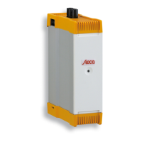
Details on product types and manufacturer information.

Device Safety Labels

Visual warnings and safety information displayed on the device itself.

Certificates and Optional Accessories

Product Certifications and Compliance

Information on product certifications and compliance standards.

Available Optional Accessories

Listing of additional accessories that can be used with the inverter.

2.3 Scope of Delivery

2.4 Intended Use

2.5 About This Manual

Manual Contents Overview

Provides an overview of the sections and topics covered in the manual.

Target Group and Symbols

Manual Target Audience

Defines the intended audience and required expertise for using the manual.

Warning and Device Symbols Explanation

Explains warning signs and symbols used in the manual and on the device.

Signal Words and Abbreviations

Signal Word Definitions

Defines signal words (DANGER, WARNING, NOTICE) and their meanings.

Document Abbreviations List

Lists and defines abbreviations used throughout the document.

3 Structure and Function

3.1 coolcept Housing Details

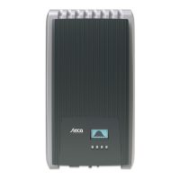
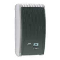
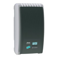
Details the housing components and connections for the coolcept model.

3.1.2 coolcept-x Housing Details

3.2 Operating Buttons Functionality

3.3 Display Information

3.3.1 Display General Information

General information about the inverter's display functionality.

3.3.2 Display Status and Information Details

Graphical Yield and Event Messages

Graphical Yield Data Representation

Explains how to view yield data graphically.

PV Generator Characteristic Curve Display

Explains how to view the PV generator characteristic curve.

Event Message Interpretation and Types

Describes how event messages are displayed, their meaning, and types.

3.3.3 Settings and Measurement Selection

Numerical Settings Configuration

Describes how to configure numerical settings like remuneration and date.

Measurement Selection for Status Display

Allows selection of measurements to be shown in the status display.

Device Settings and Network Configuration

Acoustic Alarm and Backlight Settings

Configuration and behavior of the acoustic alarm and display backlight.

TCP/IP Network Connection Setup

Network settings for communication and internet portal access.

3.3.4 Service Menu Operations

Power Limiter and Fixed Voltage Modes

Configuration Settings Management

Country and Factory Reset Procedures

Procedures for deleting country settings and resetting to factory defaults.

Voltage and Frequency Limit Configuration

Configuration of voltage and frequency limits for grid connection.

Reactive Power Control and Cooling System

Reactive Power Characteristic Curve Setup

Setting up reactive power characteristic curves for grid compliance.

3.4 Inverter Cooling System Function

Explanation of the inverter's cooling system and thermal management.

Grid Monitoring and Data Communication

3.5 Grid Monitoring Functionality

How the inverter monitors grid parameters and reacts to deviations.

3.6 Data Communication Overview

Overview of communication interfaces and data transmission capabilities.

3.6.1 Data Display and Logging Details

Details on displayed and logged data types and their storage resolution.

3.6.2 Network (TCP/IP) Connection Setup

HTML Interface and RS485 Bus Communication

Accessing Data via HTML Pages

How to access yield data and information via HTML pages using a browser.

3.6.3 RS485 Bus Communication Details

Information about communication via the RS485 bus.

RS485 Bus Termination and Compatibility

RS485 Bus Termination Requirements

Requirements for terminating the RS485 bus for data transmission.

Compatible Inverters for RS485 Connection

List of compatible inverters that can be connected to the RS485 bus.

RS485 Bus Connection Specifics for Italy

RS485 Bus Wiring and Data Loggers

RS485 Bus Wiring Diagram

Diagram illustrating the RS485 bus wiring configuration.

External Data Logger Integration Guide

Information on connecting external data loggers for system monitoring.

RS485 Data Connection Cable Options

3.6.4 Alternative RS485 Data Connection Cable

Details on using an alternative data connection cable for RS485.

3.6.5 RS485 Bus Termination Procedure

Procedures to prevent data transmission errors by terminating the bus.

RS485 Addressing and Modbus RTU Communication

3.6.6 RS485 Bus Addressing Procedure

How to assign unique addresses to inverters on the RS485 bus.

3.6.7 Modbus RTU Protocol Details

Communication protocol for energy meters.

3.6.8 Modbus RTU Data Connection Cable

Specifications for the Modbus RTU data connection cable.

RJ10 Plug Contact Assignment for Modbus RTU

4 Installation

4.1 Safety Measures During Installation

Crucial safety warnings and precautions before and during installation.

Installation Site Requirements and Precautions

Mounting Location Conditions and Clearance

Conditions for the mounting location and required free spaces around the inverter.

4.2 Mounting the Inverter Securely

Inverter Securing and Mounting Tips

Attaching Inverter to Mounting Plate

4.3 AC Connection Preparation

AC Plug Assembly for Grid Connection

AC Connection for 2-Phase and 3-Phase Grids

4.4 Prepare DC Connections with SUNCLIX

4.5 Data Connection Cable Preparation

4.6 Connecting Inverter and Switching AC On

4.7 Initial Commissioning of the Inverter

4.7.1 Commissioning Start Conditions

Conditions required to start the initial commissioning procedure.

Guided Initial Commissioning Steps

Overview of the guided setup process for language, date, country, etc.

Setting the Country for Grid Parameters

Instructions for setting the correct country for regional grid parameters.

Language and Date Format Configuration

Time Format and Time Setting Procedures

Country Selection Process for Operation

Reactive Power Control Configuration Options

Reactive Power Settings Details

Loading Default Reactive Power Settings

How to load default characteristic curves for reactive power.

Configuring Number of Nodes for Reactive Power Curves

Setting the number of nodes for custom reactive power curves.

Node Parameter Configuration and Commissioning Finish

Node Parameter Adjustment Procedure

Adjusting parameters for individual nodes in reactive power curves.

Displaying Characteristic Curve

Viewing the configured reactive power characteristic curve.

Finishing Initial Commissioning Procedure

Final steps to complete the inverter's initial setup.

4.8 Feed-in Management Configuration

4.9 DC Power Switch On Procedure

4.10 Deinstalling the Inverter Safely

Disconnecting Power Supplies and Removing Inverter

Safely Disconnecting Power Supplies

Safely disconnecting DC and AC power before removal.

5 Operation

5.1 Overview of Operating Functions

Diagram showing the main menu structure and available functions.

General and Important Operating Functions

5.2 General Operating Functions

General information on using buttons and navigating the interface.

5.3 Important Operating Functions

Details on operating the status display and navigating menus.

Editing Lists and Numeric Settings

Service Menu Access and Value Editing

5.4 Internet Portal

5.4.1 Portal Registration Process

Steps for registering the inverter and accessing the online portal.

Entering User Data for Portal Registration

Entering System and Site Data for Portal

Email Verification and Account Activation

5.4.2 Portal Login and Data Display

Yield Data Display and System Information

6 Self Test Procedure

Performing and Interpreting the Self Test Results

Self Test Error Prevention and Remedies

7 Fault Rectification

Event Message Interpretation and Types

Understanding the components of an event message and its types.

Displaying and Confirming Event Messages

Grid and Frequency Related Event Messages

Grid Voltage Related Event Messages

Internal, Isolation, and Temperature Event Messages

Current, Voltage, and Communication Event Messages

8 Maintenance and Disposal

8.1 Inverter Maintenance Procedures

Instructions for cleaning and maintaining the inverter.

Dust Removal Procedures

Method for removing dust from the inverter cooling fins.

Heavy Soiling Cleaning Instructions

Procedures for cleaning significant dirt or grime.

8.2 Proper Inverter Disposal Guidelines

Guidelines for the proper disposal of the inverter.

9 Technical Data

9.1 Inverter Specifications

Technical specifications for the inverter series.

9.1.1 StecaGrid 1500/1500x/2000/2000x Data

Detailed technical specifications for the 1500/2000 series inverters.

1500/2000 Series Performance and Efficiency Data

1500/2000 Series Operating Conditions and Safety

Connection and Interface Specifications

9.1.2 StecaGrid 2500/2500x/3010/3010x Data

2500/3010 Series Performance and Efficiency

2500/3010 Series Operating Conditions and Safety

9.1.3 StecaGrid 3600/3600x/4200/4200x Data

3600/4200 Series Output and Power Specifications

3600/4200 Series Efficiency and Operating Conditions

3600/4200 Series Connections and Safety Features

9.2 AC Cable and Circuit Breaker Recommendations

9.3 Country Table for Specific Settings

10 Liability and Warranty Information

11 Contact and Support Information

Appendix

A Assembly Instructions

A.A Bore Dimension Drawing for coolcept

Dimensional drawing for mounting hole placement on coolcept devices.

A.B Bore Dimension Drawing for coolcept-x

A.C AC Plug Specifications and Assembly

AC Plug Installation and Connector Handling

Housing Installation with M25 Feedthrough

A.D Phoenix Contact SUNCLIX DC Connector

Related product manuals