5
PEAK CONTROL METHOD
POWER LINE CARRIER (PLC) PEAK CONTROL
transceiver (sold separately) sends peak control and outdoor temperature information to all the heaters in
the building, eliminating the need for low voltage wiring to each heater.
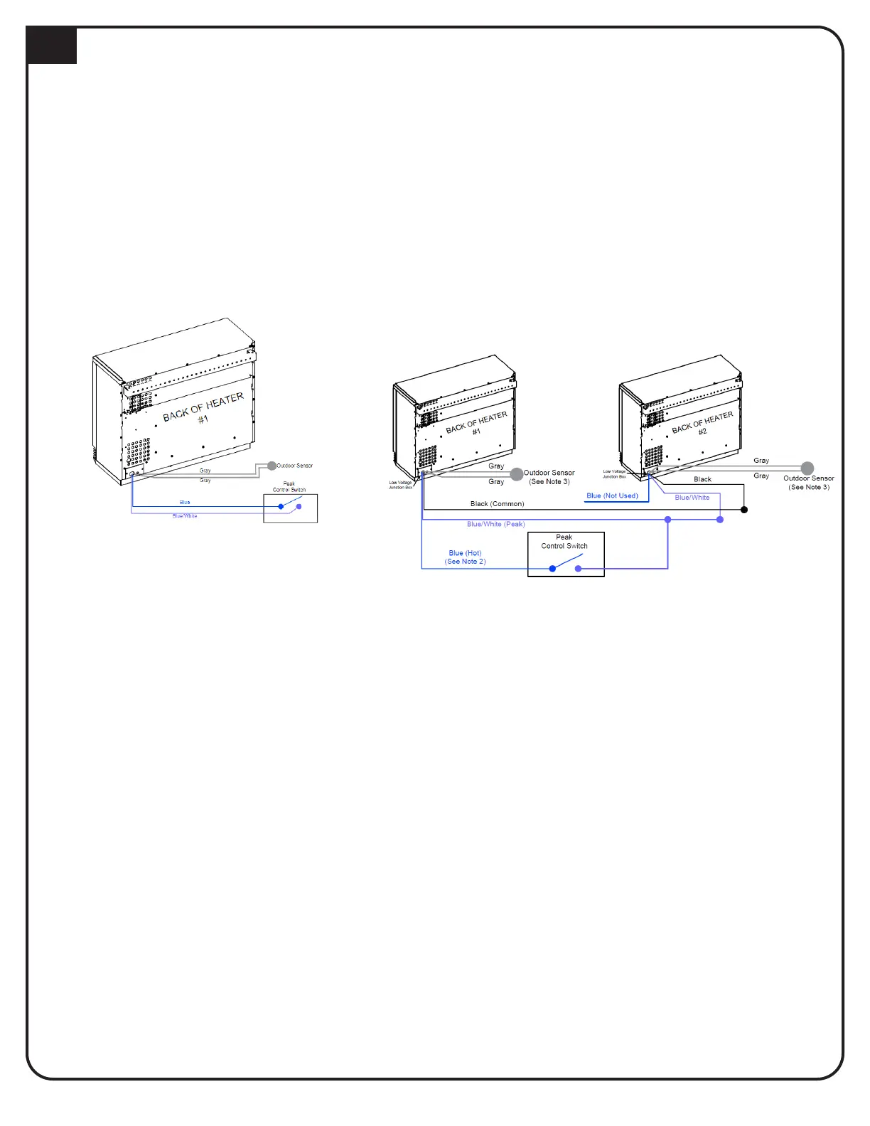
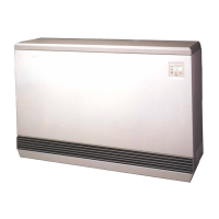
LOW VOLTAGE CONNECTIONS FOR DIRECT WIRED CONTROLS
NOTES:
1. Class II (low voltage) wiring should never enter a line voltage area of the heater, including its umbilical cord.
2. Connecting the low voltage hot (blue) wire from multiple heaters to a single control switch may cause damage
to the heater. In multiple heater applications, connect the wires as shown for proper operation.
3. In multiple heater applications, one outdoor sensor is needed for each heater installed.
4. If routing low voltage wire near line voltage conductors, shielded wire must be used.
TWO HEATERS
If using the low voltage control option, the heater is direct wired to the power company’s peak control switch.
Field connections from the switch are made to the heater’s low voltage wiring harness through the low
voltage raceway. These wires are also accessible from inside the electrical compartment.
heater. Peak control times are programmed into the heater to enable this device. Refer to the instructions
provided with the time clock module for more information on the installation and operation of this device.
TIME CLOCK MODULE PEAK CONTROL
LINE VOLTAGE PEAK CONTROL
age to the charging circuit(s) during the peak times. If line voltage control is used, the blower/control circuit
of the heater must be powered with a separate, uninterrupted, circuit. The display on the heater will continu
7
SINGLE HEATER