Field Wiring
Step 1 After establishing placement of the heater, mount a eld
connection junction box in a location where heater-to-eld
wiring connections can be made easily. The junction box can be
located beside the heater, behind the heater, or mounted in the
oor below the heater. Steffes Corporation recommends a steel
junction box to provide protection against overheating.
The junction box MUST remain accessible for future
service to the heater and MUST be sized in accordance
with all applicable electrical codes and regulations.
Step 2 Route the proper size and type of wiring from the breaker panel
to the eld connection junction box.
Step 3 Connect the eld wiring to the wiring harness (umbilical cord) of the heater inside the junction box.
Step 4 Remove the orange breaker panel label from the mounting hardware package. This label MUST be
applied in the electrical service (breaker) panel and marked accordingly to identify the branch circuits
feeding the room heating unit.
Installation 2.05 2100 Series
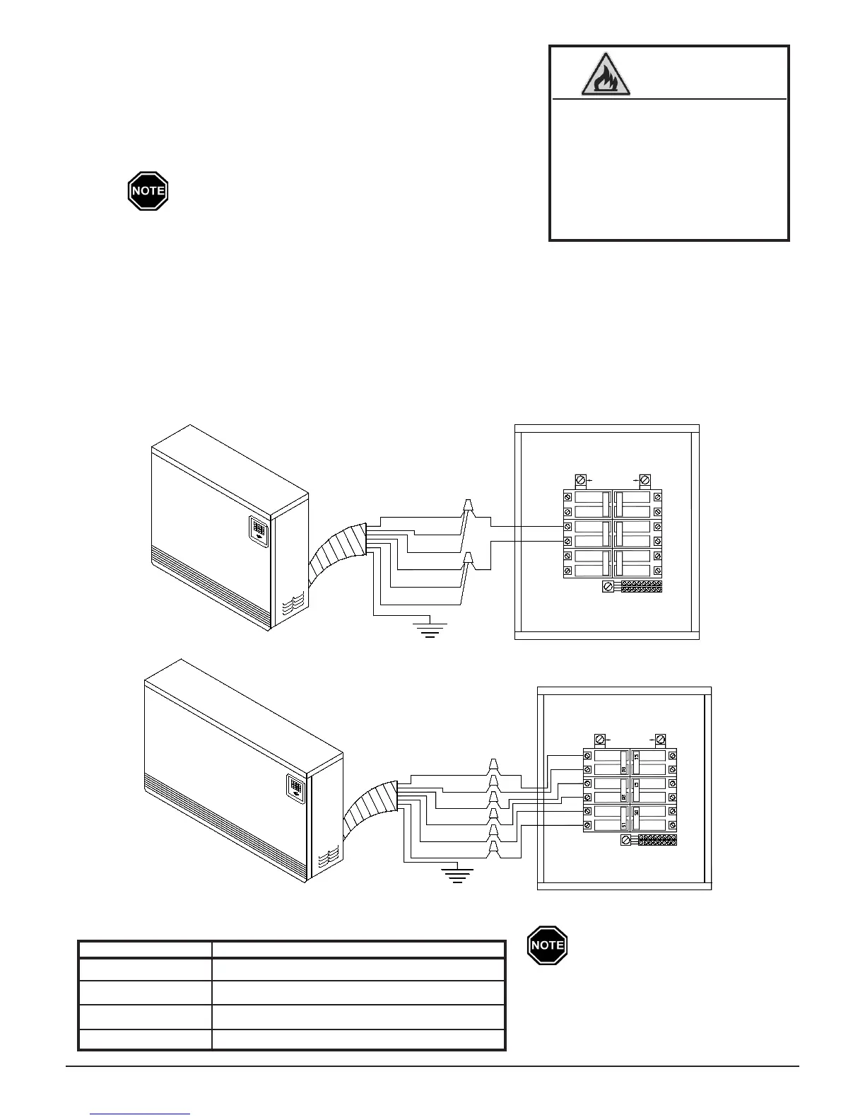
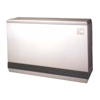
Typical System Wiring Diagram
Figure 5
Riskofinjuryorre.Poor
or marginal electrical
connections will cause the
connection to overheat and
fail. Use extreme caution
when making all electrical
connections.
WARNING
Wiring Harness (Umbilical Cord ) Color Code Chart
WIRE COLOR CIRCUIT DESCRIPTION
Black Circuit feed for two of the four heating elements
Red Circuit feed for two of the four heating elements
Blue and Blue/Black Circuit feed for the blower and heater's control
Green Ground
Connections shown are for sys-
tems with a 240V/208V blower/
control circuit. Refer to the Unit
Identication Label on the lower
left side panel of the heater for
proper voltage conguration.
RED
RED
BLACK
BLUE/BLACK
GREEN
3
15
30
6
BLACK
BLUE
CIRCUIT
SINGLE
CONNECTED
BREAKER PANEL
4
1
2
20
15
5
20
15
240VAC SOURCE
GREEN
MULTIPLE
CONNECTED
CIRCUIT
4
240VAC SOURCE
BREAKER PANEL
BLACK
BLUE/BLACK
BLUE
BLACK
RED
RED
2
3
1
6
5