Installation
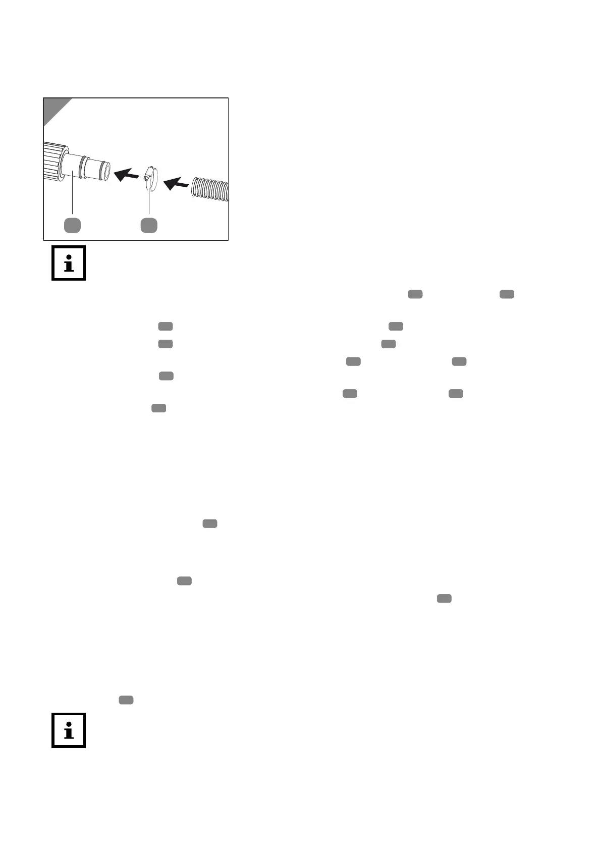
Installing adapter on hose end
When using a filter system, this must be connected upstream from the heat pump so
that the filtered water flows through the heat pump.
1. Remove coarse dirt from the connection points of the heat pump 1 , the adapters 2 and the
hose ends of the water pipes.
2. Screw an adapter
2 onto the output of the water connection 6 .
3. Screw an adapter
2 onto the input of the water connection 7 .
4. Connect the hose end of the drain with a hose clamp 3 and the adapter 2 to the water
connection output
6
(see Fig.1).
5. Connect the hose end of the feed with a hose clamp
3 and the adapter 2 to the water
connection input 7 (see Fig.1).
The adapters are installed on the hose ends.
Connecting the lines
Establishing the power supply
The MINI heat pump cannot be operated with an external timer and must be switched on/off via
the RCD adapter.
1. Connect the RCD adapter
C to the voltage supply set up at the installation site.
The power supply has been established.
Connecting a drain hose for condensate (optional)
1. Insert the drain spout 4 into the hole in the base plate.
2. Attach the drain hose (garden hose) for condensate to the drain spout 4 .
The drain hose for the condensate is connected.
Display
Standby mode
When in Standby mode, the heat pump is operationally ready but deactivated. Pressing the
On/Off button
15 switches the heat pump into the Operate mode.
After being switched on, the heat exchanger must first warm up before the heat pump is
ready for operation in the Operate mode. This process can take up to 90 seconds.
37