- 24 - - 25 -
Note on
P conductor:
The cable between two sensors must be no more than 50m in length.
No more than 25m to each further sensor. No more than 300m in total when
installing 10sensors.
Note on
S conductor:
Cable length max. 50m.
Important:
Incorrectly wired connections will produce a short circuit later on in the product
or fuse box. In this case, you must identify the individual cables and re-connect
them. An appropriate power switch for switching ON and OFF can be installed
in the supply lead.
Note for IR 180:
The mounting location should be at least 1 m away from any lights because heat
radiated from these may activate the system.
Connecting the mains power supply lead IR 180 COM1 (Fig� 4�2)
Connecting the mains power supply lead IR 180 COM 2 (Fig� 4�3)
Note on parallel connection via P conductor:
IR 180 and HF 180 can be connected in parallel. However, a neutral conductor
must be present on each flush box. When using several sensor switches, they
must be connected to the same phase. As many as 10 sensor switches can be
connected in parallel.
Master/Master COM1 (Fig� 4�4)
Master/Master COM1/COM2 (Fig� 4�5)
A parallel-connected configuration also permits the use of several masters. In
this case, each master operates the lighting group in accordance with the level
of brightness it measures. All settings are selected at each master as required.
The switched load is spread among the individual masters.
Presence is still detected collectively by all detectors. The presence output
(HLK, COM2) can be picked o from any master.
Note:
In a master/master system, inverse switching behaviour may occur on pressing
the switch (A) if the IR/HF180 have dierent stay-ON times and this has
already elapsed for one sensor. If this situation occurs, you must either wait
until the stay-ON time elapses or perform a User Reset (RC 5) or Reset (RC 8).
When interconnecting IR/HF 180, this risk is reduced by selecting the same
settings for control dials and DIP switches.
connected load ON (e.g. a light). Heat is not detected through obstacles, such
as walls or panes of glass. Heat radiation of this type will, therefore, not trigger
the sensor.
HF 180 COM1/COM2
The HF 1COM1/COM2 is an active motion detector. It responds to the
slightest movement regardless of temperature. The integrated HF sensor emits
high-frequency electromagnetic waves (5.8 GHz) and receives their echo. In
the event of the slightest movement in the detection zone, the change in echo
is perceived by the sensor.
A microprocessor then issues the switch command "switch light ON".
Movement can be detected through doors, panes of glass or thin walls.
Optionally, all function settings can be made via the remote controls RC 5, RC 8
and the Smart Remote. (➜ "7� Accessories")
Package contents for IR 180 (Fig� 3�1)
Package contents for HF 180 (Fig� 3�2)
Product dimensions for IR 180 / HF 180 (Fig� 3�3)
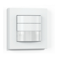
Product components (Fig� 3�4)
A Rocker switch
B Cover
C IR 180 lens / HF 180 cover
D Removal slot
E Sensor module
F Status LED
G Surround
H Metal frame
I Load module
4� Electrical connection
• Switch OFF power supply (Fig� 4�1)
Wiring up the sensor switch: Under section 6 of VDE 0100520, a multi-core
lead containing both the mains voltage leads as well as the control leads
(e.g. NYM5x1.5mm
2
) may be used for the wiring between sensor and
electronic ballast.
The mains connection terminal is designed for a maximum of 2x2.5mm².
The mains power supply lead is a cable with at least 4 conductors:
L = phase conductor (usually black, brown or grey)
N = neutral conductor (usually blue)
PE = protective-earth conductor (usually green/yellow)
P = for connecting several motion detectors
L' = switched phase conductor (usually black, brown or grey)
 Loading...