- 26 - - 27 -
Reach setting IR (Fig� 5�4 / J)
adjustable in stages
– Control dial set to maximum = max. reach (approx. 20 m)
– Control dial set to minimum = min. reach (approx. 5 m)
Reach setting HF (Fig� 5�4 / J)
Adjustable in stages
– Control dial set to maximum = max. reach (approx. 8 m)
– Control dial set to minimum = min. reach (approx. 1 m)
Time setting (Fig� 5�4 / K)
Adjustable in stages
The chosen stay-ON time can be set to between 30 s and 30 min via the
control dial. When the brightness threshold is exceeded, (presence logic), the
sensor switches OFF after the stay-ON time expires.
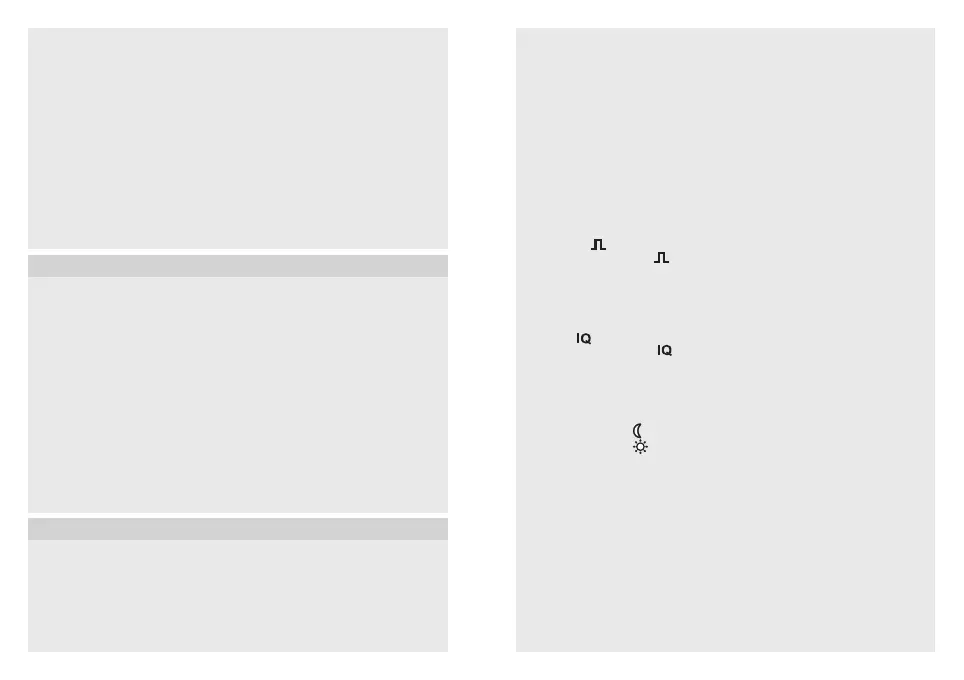
Pulse mode
If the control dial is set to , the unit is in pulse mode, i.e. the output is
switched ON for approx. 2 s (e.g. for stairwell lighting timer).
Afterwards, the sensor does not react to movement for approx. 8s. Day mode
is the only mode possible here because of dazzle by light from external
sources.
IQ mode (
)
If the control dial is set to (
), the stay-ON time is self-learning and adjusts
dynamically to user behaviour. The time cycle is determined by means of a
learning algorithm. The shortest time is 5 min, the longest time 20 min.
Twilight setting (Fig� 5�4 / L)
The chosen response threshold can be set in stages from 2-1000 lux.
– Control dial set to
= twilight mode (approx. 2 lux)
– Control dial set to
= daylight mode (approx. 1000 lux)
➜ "Example applications" table
DIP switch factory settings
DIP 1 – DIP 5 = OFF
DIP 1 – (NORM�/TEST) normal/test mode (Fig� 5�4)
Test mode has priority over all other settings on the sensor switch and is used
for verifying proper working order as well for testing the detection zone. Irre-
spective of the ambient light level, the sensor switch activates the light to stay
ON for approx. 5 s in response to movement in the room (blue LED flashes on
detecting movement). All user-selected potentiometer settings apply in normal
mode (control dials). The sensor switch can also be set by means of the blue
LED without any load connected.
The DIP-switch test mode does not end automatically.
Master/slave (Fig� 4�6�)
The master/slave configuration permits detection of movement in larger rooms
(load connected = master, no load = slave). The level of brightness prevailing
in the room is only evaluated at the master. The slaves report movements
detected to the master.
Two detectors on an external stairwell lighting timer, old building / refurbish-
ment (Fig� 4�7)
Interconnection with Control PRO sensors (Fig� 4�8)
If the IR 180 / HF 180 is interconnected with a Control PRO Sensor via the
P conductor, all switches connected to the wall switch as well as internal
switches must be deactivated (Fig� 5�4). If the overall system is to be provided
with a switch for manual override, this must be connected to the S input of the
Control PRO sensor. The Control PRO Sensor must be the master and the
IR 180 / HF 180 the slave.
5� Mounting
• Check all components for damage.
• Do not use the product if it is damaged.
• Select an appropriate mounting location, taking the reach and motion
detection into consideration (Fig� 5�1)
Mounting procedure
• Separate the sensor and load module (Fig� 5�2)
• Switch OFF power supply (Fig� 4�1)
• Connect to mains power supply (Fig� 4�2 / 4�3)
• Push load module (H) into the flush box (Fig� 5�3)
• Screw to support ring with box fixing screws (Fig� 5�3)
• Select control dial and DIP switch settings on the sensor module (E)
(Fig� 5�4) (➜ "6� Function")
• Fit the sensor module (E) into the surround (G) and press together with
the load module (H) (Fig� 5�5)
• Switch ON power supply (Fig� 5�6)
6� Function
Factory settings for control dials
Reach setting (J): IR 20 m / HF 8 m
Time setting (K): 30 s
Twilight setting (L): Daylight operation
Stay-ON time COM2 15 min
Switch-ON delay COM2 0 min
 Loading...